RF home automation system with replicable controllers

a home automation and controller technology, applied in the field of wireless home automation systems, can solve the problems of reducing the quality of the system, reducing the capacity of the amount of data which can be comprised in signals, and low bandwidth, so as to reduce the cost, reduce the quality, and reduce the effect of cos

Inactive Publication Date: 2005-12-27
SILICON LAB INC
View PDF51 Cites 152 Cited by
  • Summary
  • Abstract
  • Description
  • Claims
  • Application Information

AI Technical Summary

Benefits of technology

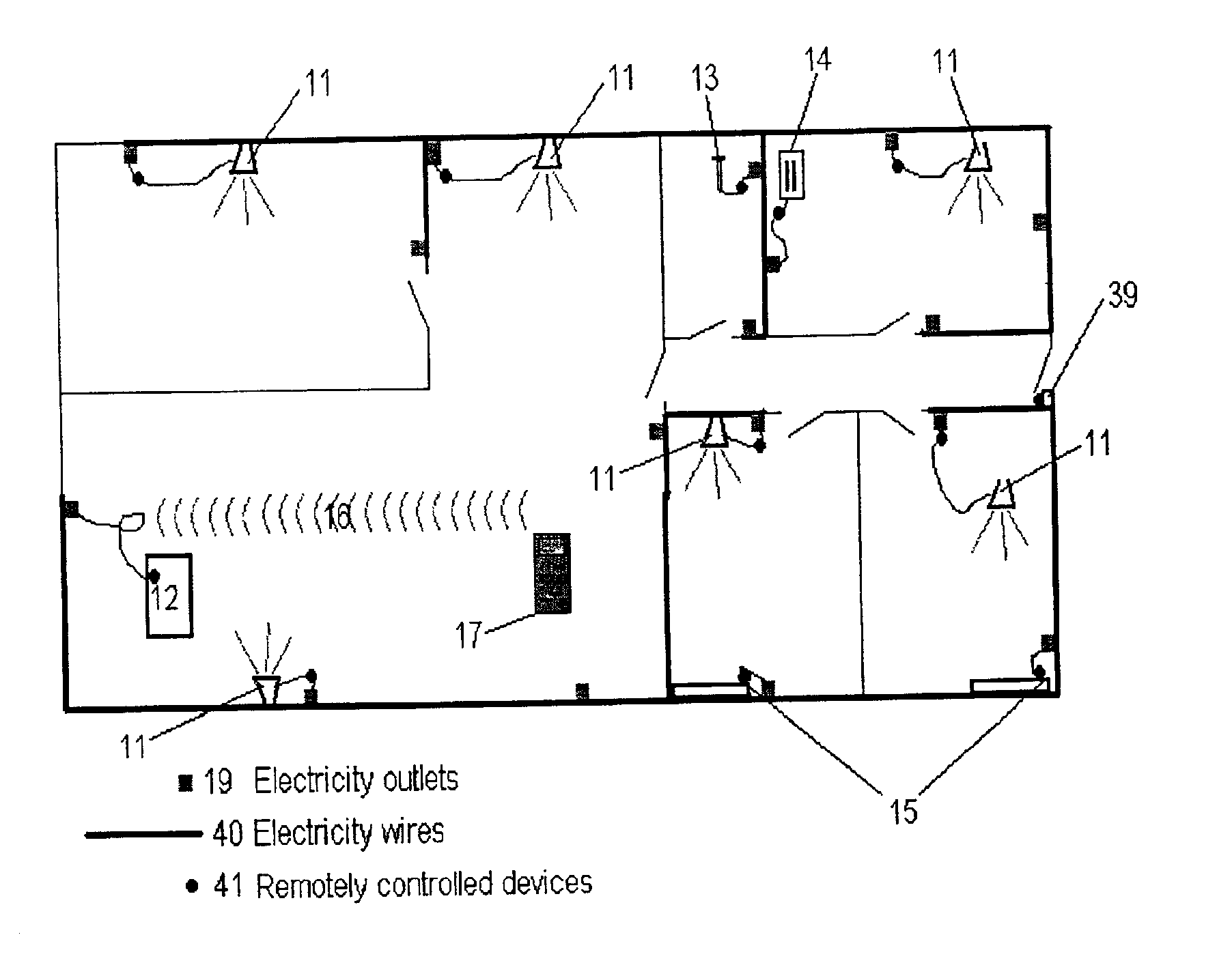
[0018]The present invention provides a high quality, low cost wireless automation system using radio frequency (RF) signals. In order to reduce the price, the system according to the present invention preferably operates at bandwidth dedicated for control commands i.e. a bandwidth around 10 kbps. Such a low bandwidth allows for chips which can be mass produced at lower prices than chips for large bandwidth systems. Also, RF transmitters and receivers of the system preferably operate within a “public” frequency range wherein a license is not required, thereby further reducing cost.
[0023]To overcome those problems, the system according to the present invention is optimized to ensure a high reliability, range / coverage, versatility, and flexibility.
[0026]It is a further object of the present invention to provide a wireless home automation system for controlling and monitoring equipment and appliances, comprising an overall architecture and programming which allows for easy configuration, synchronization, and expandability when more than one controller is included in the system.
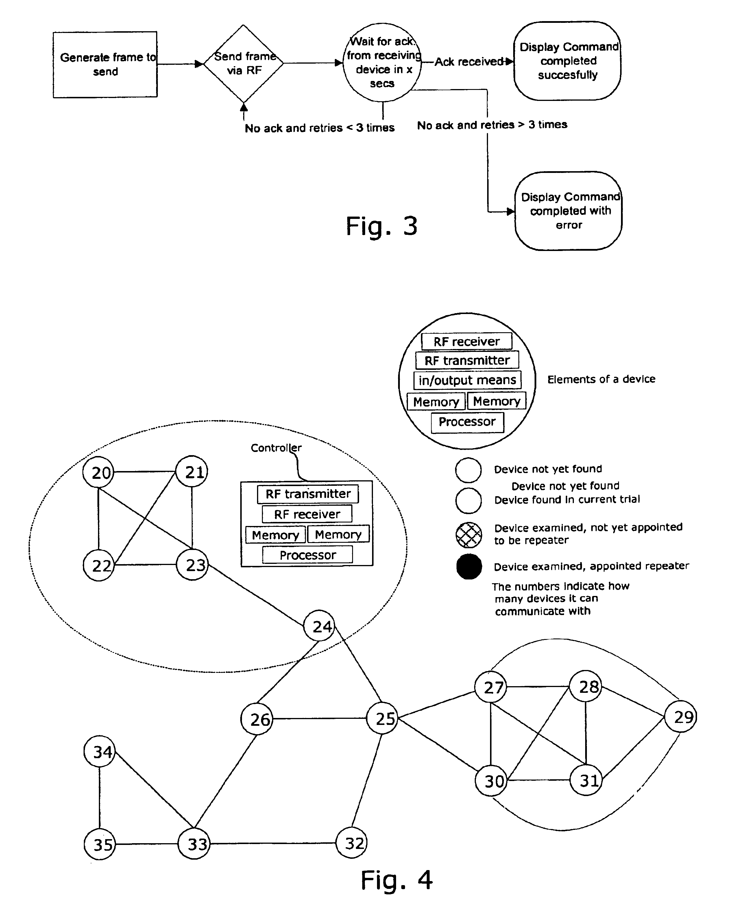
[0068]According to the first aspect, the first and second controller preferably comprises a display, means for displaying a plurality of menus having a two or more entries on the display, two or more actuators for navigating in said menus and for selecting said entries, and routines or programs stored in said processor which can be activated by selecting appropriate entries in appropriate menus. Preferably said routines or programs is operationally connected to said means for generating a signal addressed to one or more devices or to a controller so that the user can control the system by selecting entries using the actuators. Preferably, one or more of said routines or programs is operationally connected to said means for generating one or more signals comprising data to be copied from the first controller to the second controller, so that the user can update or replicate the second controller by selecting entries using the actuators.
[0070]Thus, according to the second aspect, the present invention relates to a method for updating or replicating the data held in the organized data structure in the memory the second controller from the memory of the first controller. This allows the second controller to control at least the same devices as the first controller.

Problems solved by technology

However, choosing low bandwidth operation in a public frequency range introduces a number of problems which may reduce the quality of the system:A low bandwidth gives a low capacity in the amount of data which can be comprised in signals.A large number of apparatuses operate in public frequency ranges resulting in a large amount of radio frequency interference.The allowed transmission power of RF transmitters is restricted which results in a limited signal range.

Method used


Image

  • RF home automation system with replicable controllers
  • RF home automation system with replicable controllers
  • RF home automation system with replicable controllers

Examples


first embodiment

[0117]The communication protocol of the first embodiment has a general format for the frames carrying the instructions and information between the devices of the system.

[0118]The frame format according to the first embodiment can be described as:

[0119]

TABLE 1

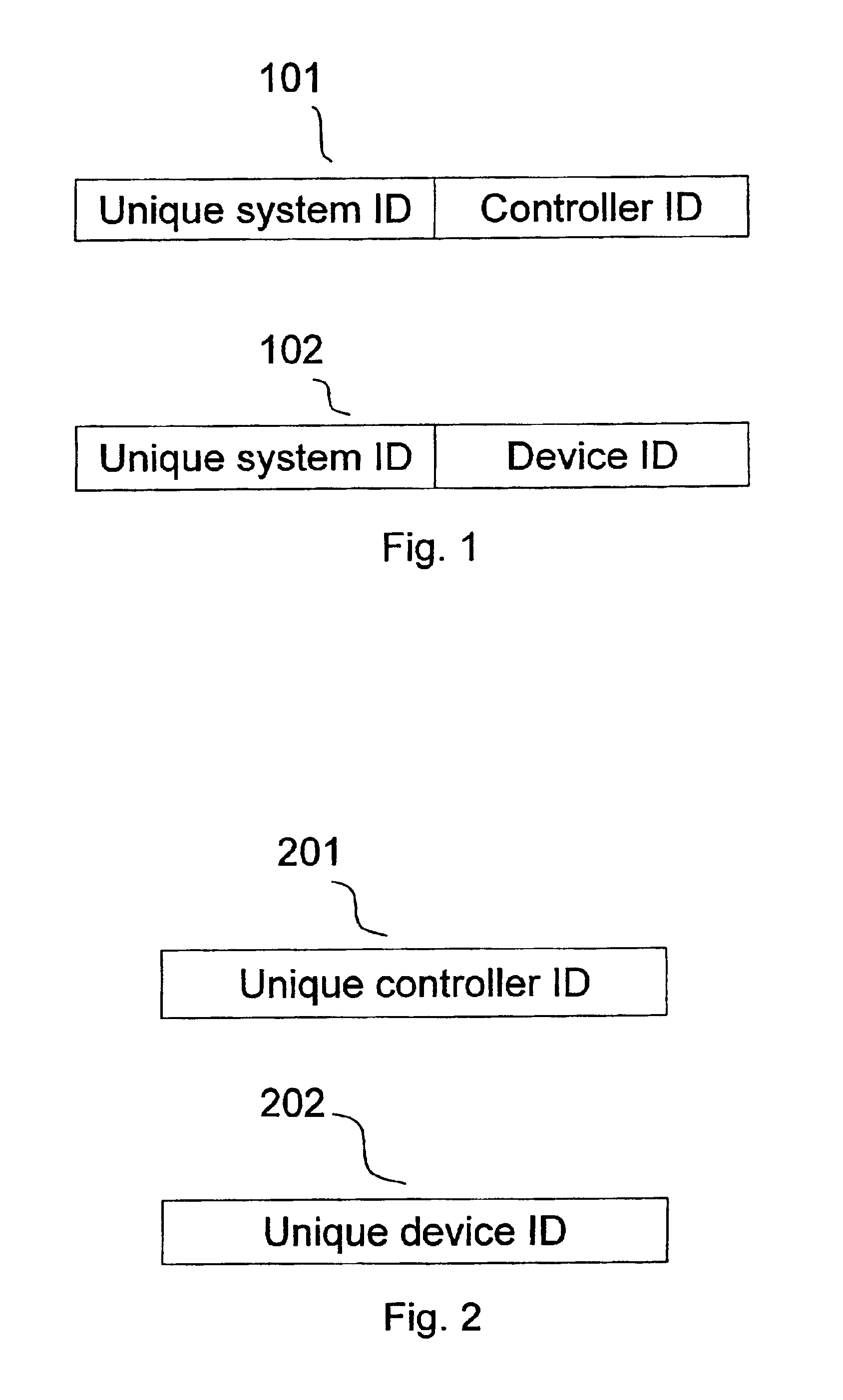
Wherein:[0120]The numbers 0 through 15 represent a bit-scale giving the order and sizes of each part of the frame. The order in which the parts appear are not restrictive and different orders can be used.[0121]Home ID (32 bit): The Home ID of the system in which this frame should be executed / received.[0122]Source ID (8-bit): The identifier (second part of the two-part identifier) of the transmitting controller or device.[0123]Version (3 bit): Protocol / frame format version. This gives the freedom to change the frame format according to an update of the software protocol or other infrastructure enhancements.[0124]Dir. (1 bit): Direction of command; 0 when a command is issued, 1 when a command is acknowledged.[0125]Type (4 bit): Th...

second embodiment

[0249]The following description of the Power & Lighting control system mainly deals with those aspects not comprised in the high-level description of general parts of the conceptual, scaleable system given in the description of the first preferred embodiment of the automation system. However, details and features described only in relation to the second embodiment are also valid with respect to the first preferred embodiment.

[0250]The Power & Lighting control system consists of the following elements.

Controllers

[0251]In the Power & Lighting embodiment, the controller is a mobile control panel such as a remote control, so that the use or programming of the system is not restricted to certain locations. Controllers have a display such as an LCD (Liquid Crystal Display) display. The controllers can optionally interface with a computer; moreover, a computer may also act as a controller in the system. The initial implementation and often also later setting of a device is carried out in t...


PUM


Abstract

The present invention relates to a wireless home automation system having controllers for controlling a broad variety of functions via two-way communication with a plurality of devices. More specifically, the invention relates to sharing information related to the system between controllers, e.g. by updating a second controller with the newly learned information of a first controller, or by replicating a controller by making a second controller a complete copy of a first controller. The information can be shared by generating and transmitting, with a first controller, a list of device identifiers of devices controlled by the first controller to a second controller. The list is received by the second controller and stored in a memory of the second controller dedicated to store device identifiers of devices controlled by the second controller. This function proves advantageous when new controllers are introduced or if a controller is lost, worn out, or destroyed.

Description

[0001]This application is a continuation-in-part of application Ser. No. 09 / 547,055 filed on Apr. 10, 2000, the entire contents of which are hereby incorporated by reference.FIELD OF THE INVENTION[0002]The present invention relates to a wireless home automation system having a controller or controlling a broad variety of functions via two-way communication with a plurality of devices. More specifically, the invention relates to systems having two or more controllers or controlling devices, wherein information related to the system can be shared between controllers.BACKGROUND OF THE INVENTION[0003]Home automation systems for controlling devices with various functions such as lighting and audio equipment within a building has evolved towards a “smart-home” concept, where different input / output (I / O) devices with a wide range of functions are remotely controlled by a central controller. Such systems are constructed as networks with a plurality of nodes which can be controllers, I / O dev...

Claims


Application Information

Patent Timeline
Patent Type & Authority Patents(United States)
IPC IPC(8): G05B15/02G05B19/042H04Q9/00G05B9/03
CPCG05B15/02G05B19/0426G05B2219/21042G05B2219/21073G05B2219/25081G05B2219/25181G05B2219/25196G05B2219/25208G05B2219/25211G05B2219/2642G05B2219/32234G05B2219/37252H04B7/15507
Inventor CHRISTENSEN, CARLOS MELIAKNUDSEN, JESPER
Owner SILICON LAB INC
Why Eureka
Try Eureka