EMI shield for transceiver

a transceiver and shield technology, applied in the direction of electrical apparatus casings/cabinets/drawers, hermetically sealed casings, printed circuit non-printed electric components association, etc., can solve the problem of interference with other electronic equipment by radiation

Inactive Publication Date: 2005-12-27
NEOPHOTONICS CORP
View PDF5 Cites 21 Cited by
  • Summary
  • Abstract
  • Description
  • Claims
  • Application Information

AI Technical Summary

Problems solved by technology

The EM radiation may interfere with other electronic equipment.

Method used


Image

  • EMI shield for transceiver
  • EMI shield for transceiver
  • EMI shield for transceiver

Examples


Embodiment Construction

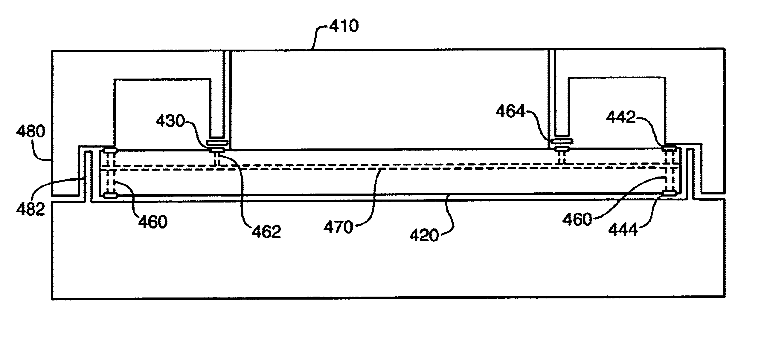
[0011]A metal shield is used for reducing EMI from a transmitter or transceiver. The integrated circuit package for the transmitter / transceiver comprises a printed circuit board, a non-metal connector, and a metal casing. The printed circuit board includes a ground ring around the non-metal connector. The metal casing substantially encloses the printed circuit board and has an opening that allows access to the non-metal connector. The metal casing has a metal lip that makes physical and electrical contact with the ground ring of the printed circuit board. In one embodiment, a second metal shield may be employed to reduce clock jitter.

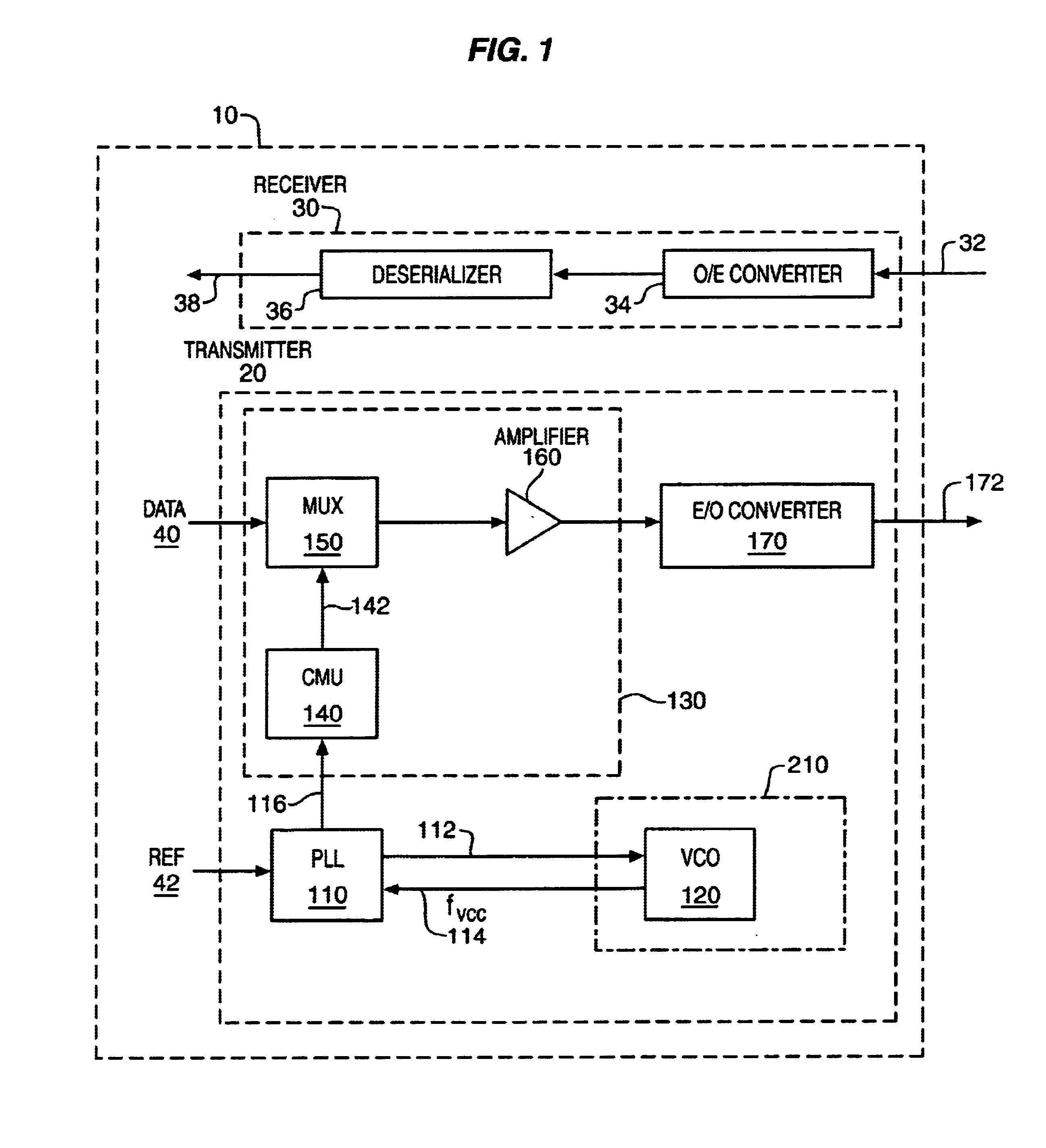
[0012]FIG. 1 is a schematic diagram showing one embodiment of a transceiver 10. The transceiver 10 comprises a transmitter 20 and a receiver 30. The receiver 30 receives optical data 32, converts it to electrical data via an optical-to-electrical converter 34, and deserializes the electrical data with a deserializer 36 to provide an electrical signal 38...


PUM


Abstract

An integrated circuit packages comprises a printed circuit board, a non-metal connector, and a metal casing. The printed circuit board includes a ground ring around the non-metal connector. The metal casing substantially encloses the printed circuit board, and has an opening that allows access to the non-metal connector. The metal casing has a metal lip that makes physical and electrical contact with the ground ring of the printed circuit board. The metal casing may be used to help reduce EMI from a transmitter.

Description

BACKGROUND OF THE INVENTION[0001]1. Field of the Invention[0002]The described invention relates to the field of integrated circuits. In particular, the invention relates to reducing electromagnetic interference (EMI) from a transmitter.[0003]2. Description of Related Art[0004]A transmitter operating at high frequencies, such as 10 Ghz, emits electromagnetic (EM) radiation from its integrated circuit package. The EM radiation may interfere with other electronic equipment. Thus, reducing EMI from a high-frequency transmitter is important.BRIEF DESCRIPTION OF THE DRAWINGS[0005]FIG. 1 is a schematic diagram showing one embodiment of a transceiver.[0006]FIG. 2 is a 3-D diagram of a transceiver showing a metal shield 210 positioned to cover the oscillator 120.[0007]FIG. 3 is a 3-D diagram that shows one example of a metal shield.[0008]FIG. 4 is a 3-dimensional diagram showing a cutaway view of a transceiver.[0009]FIG. 5 is a cross-sectional side-view of the transceiver of FIG. 4.[0010]FIG...

Claims


Application Information

Patent Timeline
Patent Type & Authority Patents(United States)
IPC IPC(8): H01L23/552H05K9/00
CPCH01L23/552H05K9/0007H01L2924/0002H01L2924/00
Inventor SCHULTZ, CRAIG L.PETIT, TODD MICHEALOEN, JOSHUA T.
Owner NEOPHOTONICS CORP
Why Eureka
Try Eureka