Pipelined packet switching and queuing architecture

a packet switching and queuing technology, applied in the field of communication devices, can solve the problems of inability of a general purpose digital computer to perform the necessary lookup and queue management functions using software in real time, lack of flexibility in prior art systems tuned for hardware speed, and inability to meet the demands of modern internetworking systems. achieve the effect of rapid implementation of new features and capabilities, and high throughpu

Inactive Publication Date: 2005-12-27
CISCO TECH INC
View PDF5 Cites 185 Cited by
  • Summary
  • Abstract
  • Description
  • Claims
  • Application Information

AI Technical Summary

Benefits of technology

[0025]The architecture of the present invention has the advantages of high throughput and the ability to rapidly implement new features and capabilities.

Problems solved by technology

One shortcoming of prior art packet routing / switching systems has been the inability of a general purpose digital computer to perform the necessary lookup and queue management functions using software in real time, i.e., approaching the wire speed (line rate) of the incoming packets.
As the need for increased packet throughput has grown, software-based systems have been shown to lack sufficient scalability to the demands of modern internetworking systems.
A further drawback is the lack of flexibility in prior art systems tuned for speed with hardware implementations of functions once performed by software.
As the hardware is less able to be reconfigured without redesign, these prior art designs are often rendered obsolete by the adoption of new standards and communications protocols.
A still further drawback of prior art systems is their relative inability to rapidly provide a range of services based on packet priority, as represented by various fields in the packet header.

Method used


Image

  • Pipelined packet switching and queuing architecture
  • Pipelined packet switching and queuing architecture
  • Pipelined packet switching and queuing architecture

Examples


Embodiment Construction

[0057]The following sets forth a detailed description of at least the best contemplated mode for carrying out the one or more devices and / or processes described herein. The description is intended to be illustrative and should not be taken to be limiting.

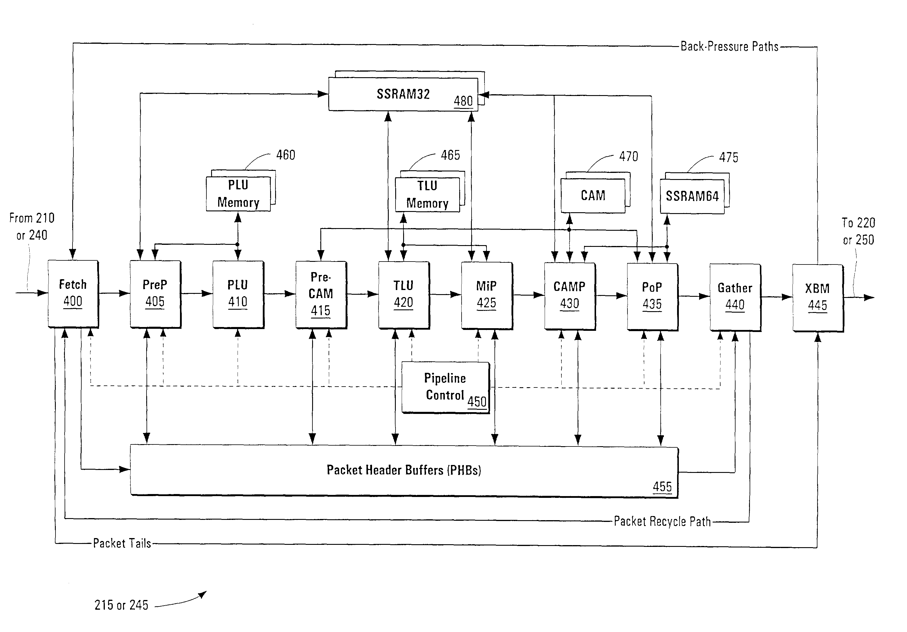
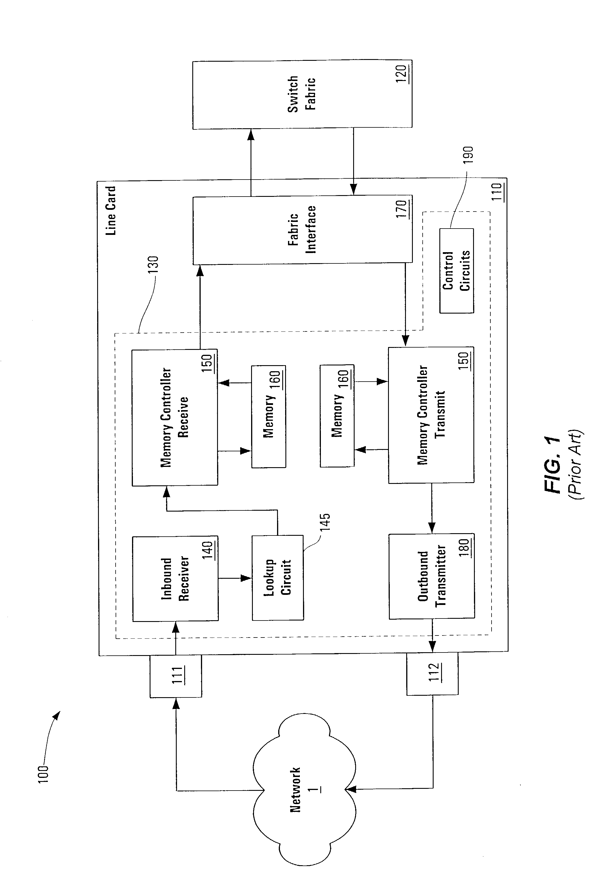
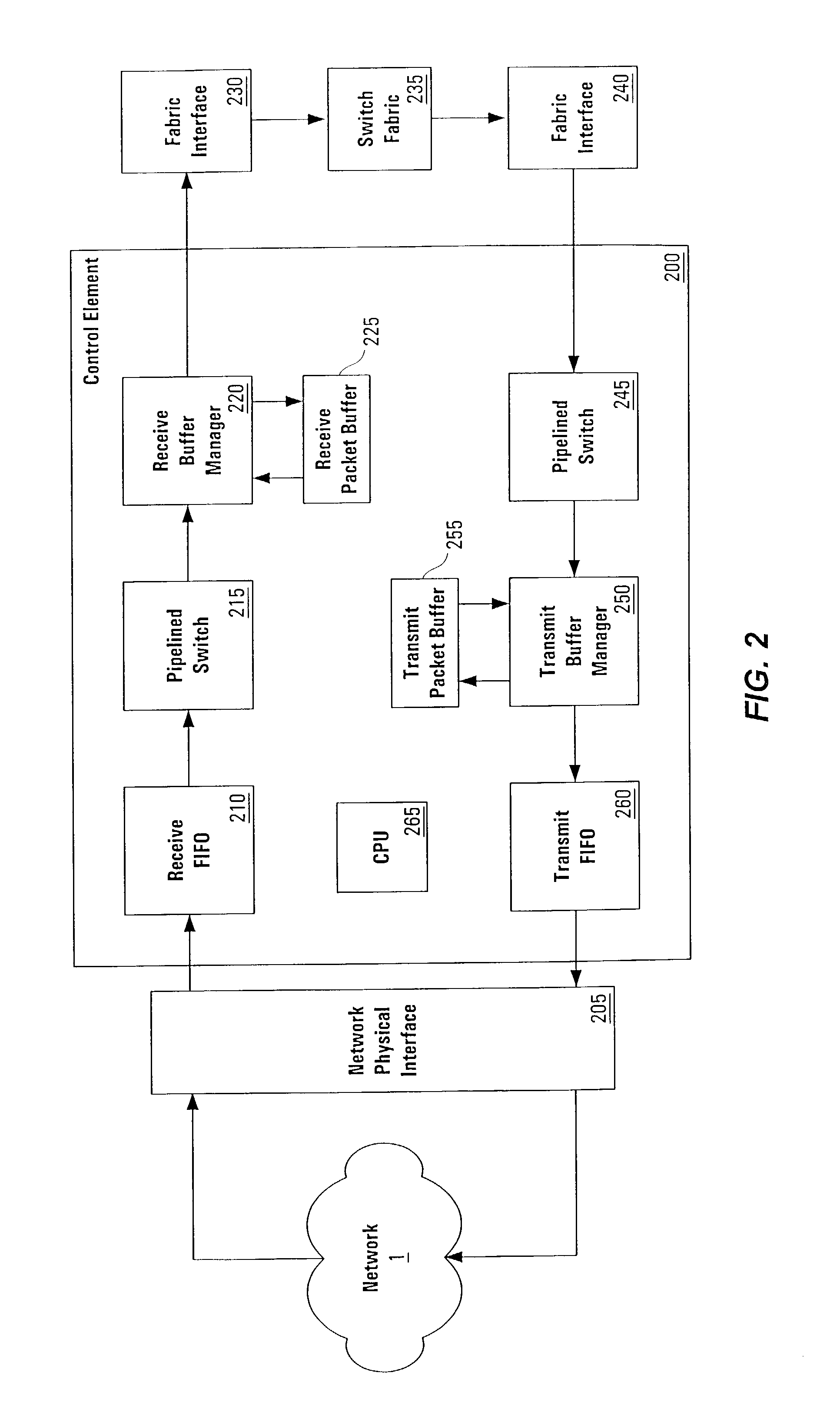
[0058]The present invention is an architecture for a linecard in a network communications device such as a router or switch. The linecard provides an interface between a routing or switching device and a network that operates bi-directionally, both receiving a data stream (e.g., packets) from the network and transmitting a data stream to the network. Typical devices comprise multiple linecards (and thus multiple network connections) and a single switching interconnect core or “fabric” that provides the physical connection between linecards.

[0059]Among the more desirable “edge” features that can be supported by the systems and methods of the present application are: access control lists (ACLs) or extended access control lists (Ex-ACL...


PUM


Abstract

A pipelined linecard architecture for receiving, modifying, switching, buffering, queuing and dequeuing packets for transmission in a communications network. The linecard has two paths: the receive path, which carries packets into the switch device from the network, and the transmit path, which carries packets from the switch to the network. In the receive path, received packets are processed and switched in a multi-stage pipeline utilizing programmable data structures for fast table lookup and linked list traversal. The pipelined switch operates on several packets in parallel while determining each packet's routing destination. Once that determination is made, each packet is modified to contain new routing information as well as additional header data to help speed it through the switch. Using bandwidth management techniques, each packet is then buffered and enqueued for transmission over the switching fabric to the linecard attached to the proper destination port. The destination linecard may be the same physical linecard as that receiving the inbound packet or a different physical linecard. The transmit path includes a buffer / queuing circuit similar to that used in the receive path and can include another pipelined switch. Both enqueuing and dequeuing of packets is accomplished using CoS-based decision making apparatus, congestion avoidance, and bandwidth management hardware.

Description

[0001]This application is a continuation-in-part of application Ser. No. 09 / 503,552, filed Feb. 14, 2000, and entitled “Pipelined Packet Switching And Queuing Architecture,” naming Garry P. Epps and Michael Laor as inventors, hereinafter referred to as the “'552 application.” The above-referenced applications are hereby incorporated by reference herein in their entirety.BACKGROUND OF THE INVENTION[0002]1. Field of the Invention[0003]The present invention relates to communications devices, specifically devices that enable packet forwarding and handling in communications networks.[0004]2. Description of the Related Art[0005]In a communications network, routing devices receive messages at one of a set of input interfaces and forward them on to one or more of a set of output interfaces. Users typically require that such routing devices operate as quickly as possible in order to keep up with the high rate of incoming messages. In a packet routing network, where information is transmitted...

Claims


Application Information

Patent Timeline
Patent Type & Authority Patents(United States)
IPC IPC(8): H04L12/28H04L12/56
CPCH04L12/5693H04L47/10H04L47/21H04L47/326H04L47/527H04L47/6215H04L49/1546H04L49/3009H04L49/90H04L49/9078H04L49/205H04L49/3018H04L49/3063H04L49/50H04L49/552H04L49/602H04L47/50
Inventor BELZ, DAVIDEPPS, GARRY P.LAOR, MICHAELOREN, EYAL
Owner CISCO TECH INC
Why Eureka
Try Eureka