Antenna device and method for transmitting and receiving radio waves

a radio wave and antenna technology, applied in the field of antenna devices, can solve the problems of complex receiver circuitry structure, inability to adapt the antenna later on to any specific, and inability to optimally use the antenna, etc., and achieve the effects of convenient installation and reliable, mechanical durability, and easy manufactur

Inactive Publication Date: 2005-12-27
SAMSUNG ELECTRONICS CO LTD
View PDF37 Cites 94 Cited by
  • Summary
  • Abstract
  • Description
  • Claims
  • Application Information

AI Technical Summary

Benefits of technology

[0014]It is still a further object to provide an antenna device that is simple, lightweight, easy to manufacture and inexpensive.
[0015]It is yet a

Problems solved by technology

It is thus a formidable task to manufacture such compact and versatile terminals, which exhibit good antenna performance under a variety of conditions.
This means that the antenna cannot later on be adapted to any specific condition under which a certain telephone is to be used or to suit a different hand-portable telephone.
Thus, each model of a hand-portable telephone must be provided with a specifically designed antenn

Method used


Image

  • Antenna device and method for transmitting and receiving radio waves
  • Antenna device and method for transmitting and receiving radio waves
  • Antenna device and method for transmitting and receiving radio waves

Examples


Embodiment Construction

[0027]In the following description, for purposes of explanation and not limitation, specific details are set forth in order to provide a thorough understanding of the present invention. However, it will be apparent to one skilled in the art that the present invention may be practiced in other embodiments that depart from these specific details. In other instances, detailed descriptions of well-known devices and methods are omitted so as not to obscure the description of the present invention with unnecessary details.

[0028]As used herein, the expression “antenna structure” is intended to include active elements connected to the transmission (feed) line(s) of the radio communication device circuitry, as well as elements that can be grounded or left disconnected, and hence operate as, e.g., directors, reflectors, impedance matching elements.

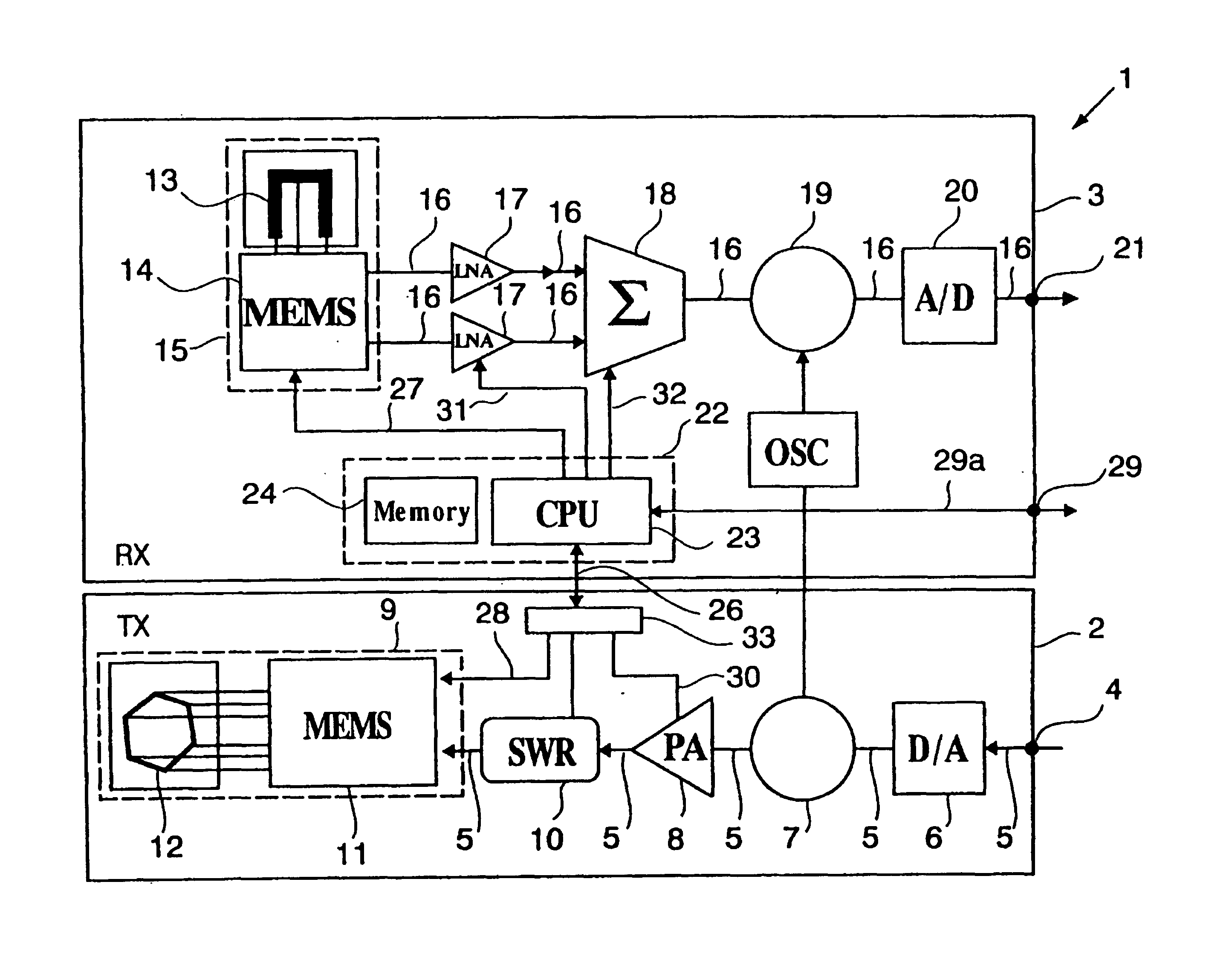
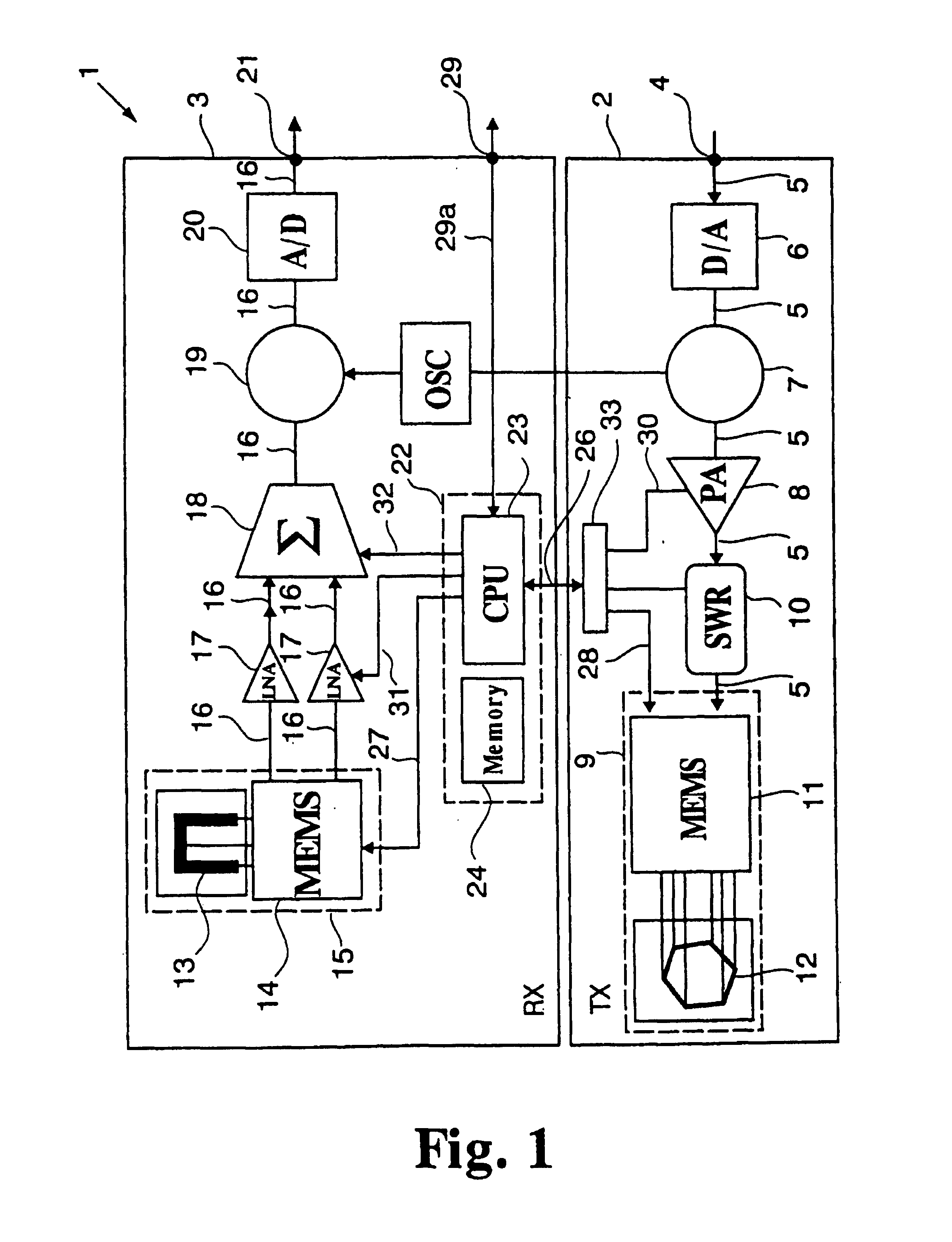
Inventive Antenna Module (FIG. 1)

[0029]With reference to FIG. 1 an antenna device or module 1 according to an embodiment of the present invention i...


PUM


Abstract

An antenna device for transmitting and receiving radio frequency waves, installable in a communication device includes an antenna structure switchable between antenna configuration states. Each state is distinguished by a set of radiation parameters, such as resonance frequency, input impedance, bandwidth, radiation pattern, gain, polarization, and near-field pattern. A switching device selectively switches the structure between the states. The antenna device includes a first receiver which receives a first measured operation parameter indicative of quality of transmission of radio frequency waves by the antenna structure, and a second receiver which receives a second measured operation parameter indicative of quality of reception of radio frequency waves by the structure. The antenna device includes a controller which controls the switching device, and selective switching of the antenna structure between the states, based on the first and second measured operation parameters, to improved transmission and/or reception quality.

Description

CROSS REFERENCE TO RELATED APPLICATIONS[0001]The present invention claims priority to commonly assigned Swedish Patent Application Serial No 9903944-8 filed Oct. 29, 1999 and is a continuation of PCT Patent Application Serial No. PCT / SE00 / 02057 filed on Oct. 24, 2000, the entire contents of all of which are hereby incorporated by reference in their entirety for all purposes. The present application is also related to commonly assigned, co-pending U.S. patent application Ser. No. 09 / 712,131 entitled “An antenna device for transmitting and / or receiving RF waves”, now U.S. Pat. No. 6,392,610; U.S. patent application Ser. No. 09 / 712,144 entitled “Antenna device for transmitting and / or receiving radio frequency waves and method related thereto”; and U.S. patent application Ser. No. 09 / 712,133 entitled “Antenna device and method for transmitting and receiving radio waves”, all of which were filed concurrently herewith. These applications are based on the following corresponding PCT applic...

Claims


Application Information

Patent Timeline
IPC IPC(8): H01Q1/24H01Q1/36H01Q3/24
CPCH01Q1/242H01Q1/36H01Q3/24H04B7/02
Inventor BRAUN, CHRISTIANEDVARDSSON, OLOVERIKSSON, LEIF
Owner SAMSUNG ELECTRONICS CO LTD
Why Eureka
Try Eureka