Scanning acoustic micro imaging method and apparatus for non-rectangular bounded files

a micro-imager and scanning acoustic technology, applied in the direction of counting objects on conveyors, instruments, specific gravity measurements, etc., can solve the problems of not being able to use signal processing analytics on the missing acoustic signal information, not being able to derive additional information from the stored x-y-z data set of amplitude peak values, and not being able to be found offlin

Inactive Publication Date: 2006-01-03
NORDSON CORP
View PDF25 Cites 118 Cited by
  • Summary
  • Abstract
  • Description
  • Claims
  • Application Information

AI Technical Summary

Problems solved by technology

However, many applications exist wherein the information desired to be retrieved from the solid part is not precisely known at the time the part is acoustically interrogated.
Since the acoustic reflectance signals returned from each pulse are lost, except for the peak of the signal within the gated region (and optionally, polarity and TOF data), it is not possible to derive additional information from the stored X-Y-Z data set of amplitude peak values.
It is not possible off-line, for example, to adjust the position of the gate to change the depth of the inspected plane.
Nor is it possible to employ signal processing analytics on the missing acoustic signal information to learn more about the anomalies which perturbed the insonifying sound pulses.
One obvious and significant disadvantage of this approach, however, is that all images generated by changing gate position are not in sharp focus.
As will become evident from the ensuing description, another drawback of moment of this last-described approach is the limited amount of data that can be gathered in a single scan of the sample.
However, there are many applications wherein the target field desired to be scanned is not rectangular, and thus does not conform to the shape of the field scan...

Method used


Image

  • Scanning acoustic micro imaging method and apparatus for non-rectangular bounded files
  • Scanning acoustic micro imaging method and apparatus for non-rectangular bounded files
  • Scanning acoustic micro imaging method and apparatus for non-rectangular bounded files

Examples


example 1

[0160]For one unique set of points in 4-space, which correlates to a unique position of the transducer (X1, Y1, Z1), there will be the 4000 values, one for each of the A-scan points captured at that position. If the capture gate is set as indicated for this sample, then there will be A-scan values that are equally spaced in time and that start before the top surface of the sample and that end after the bottom surface of the sample.

example 2

[0161]For another unique set of points in 4-space (X3, Y4, and T=‘150 samples later than the sample point that correlates to the sample surface’,) there will be 10 different values, one for each of the 10 different Z positions of the transducer used for the ten different slices.

example 3

[0162]For a third unique set of points in 4-space (Y19, Z6, and T=‘112 samples later than the sample point that correlates to the sample surface’,) there will be 256 different values, one for each of the 256 different X positions of the transducer at which data were captured.

[0163]The resulting virtual sample will thus be captured in a full 4D data set which can be processed and displayed as though the live sample were present. Having the virtual sample may in some respects be an advantage over operations in real time, as processing speeds need not be so rapid when analyzing a virtual sample off line.

AMI Scanning of Non-Rectangularly Bounded 2D and 3D Space

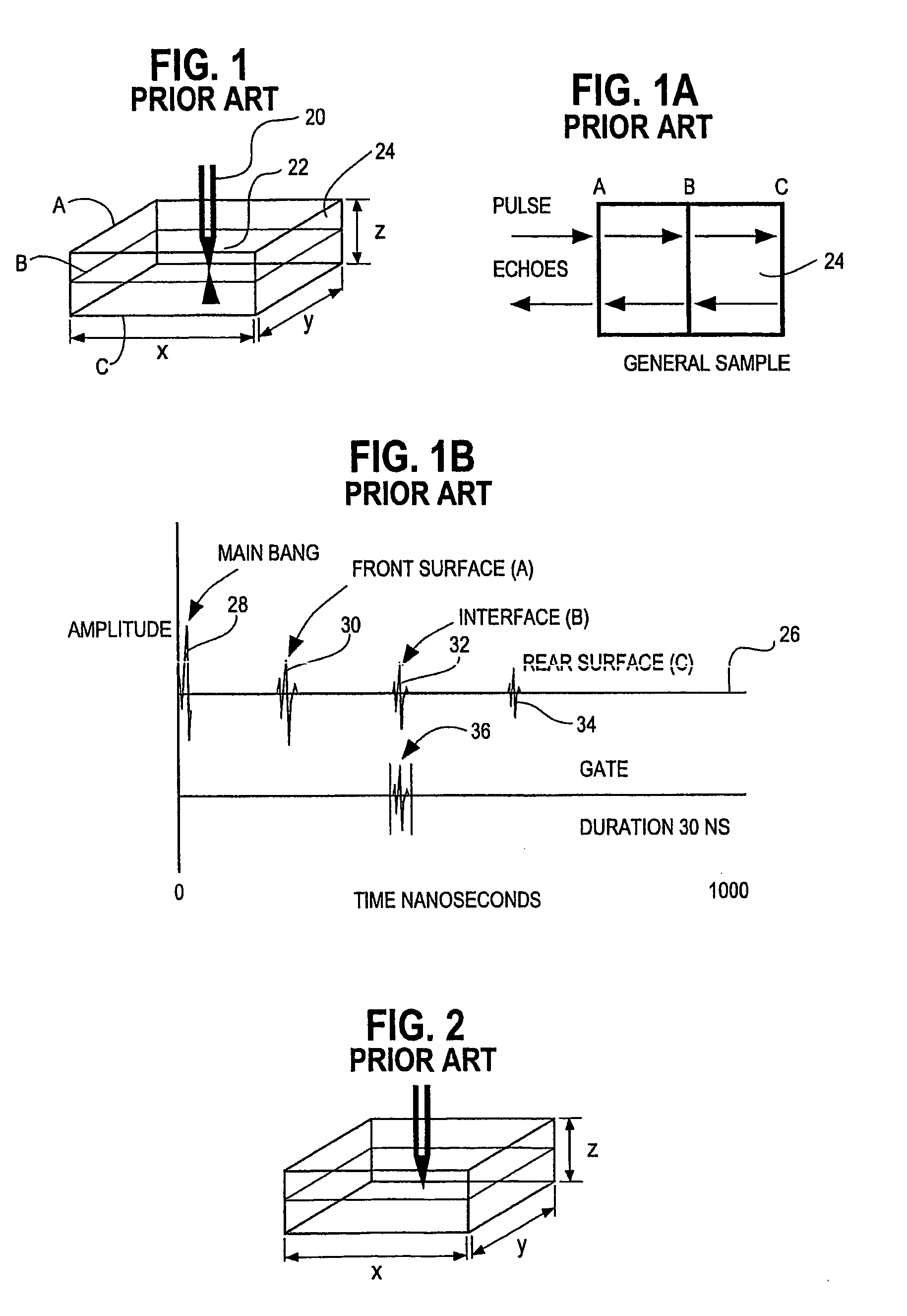
[0164]For purposes of the present application the following definitions shall apply:[0165]1) “Rectangular area” or “2D rectangular space” or “2D rectangularly bounded area” (or space) means a two dimensional area or space having right angle corners, as shown in FIG. 1, for example.[0166]2) “Rectangular volume or region” or “3D rec...


PUM


Abstract

Method and implementing apparatus useful in acquiring data on acoustic features within a sample provides a pulsed acoustic probe and a stage system for effecting relative movement between the sample and the probe. The stage system is commanded such that the probe interrogates a non-rectangularly bounded space on the sample surface or within the volume of the sample. Acoustic energy reflected from or transmitted through the sample is sensed. Amplitude signals are developed from the sensed acoustic energy. Data characterizing the developed amplitude signals are stored for subsequent processing.

Description

RELATED APPLICATIONS[0001]This application is related to, but not dependent upon, application Ser. No. 09 / 911,602, filed Jul. 24, 2001 for Acoustic Micro Imaging Method and Apparatus for Capturing 4D Acoustic Reflection Virtual Samples, and application Ser. No. 10 / 007,984, filed Nov. 13, 2001 for Frequency Domain Processing of Scanning Acoustic Micro Imaging Signals, both assigned to the assignee of the present invention.BACKGROUND OF THE INVENTION[0002]This invention concerns improvements in the field of non-destructive testing and failure analysis using pulsed ultrasound as a material probe. While many of the applications of the invention are useful in a broad range of applications, the invention will be described in the context of acoustic micro imaging (“AMI”). To further an understanding of the broad applicability of the principles of the invention, a brief description will be engaged of various scanning modes commonly employed today in AMI.[0003]The most basic form of acoustic...

Claims


Application Information

Patent Timeline
IPC IPC(8): G01N29/06
CPCG01N29/0609G01N29/0681G01N29/48G01N29/11G01N2291/044
Inventor ORAVECZ, MICHAEL G.
Owner NORDSON CORP
Why Eureka
Try Eureka