STED (stimulated emission depletion) micro imaging method and device based on radially polarized vortex beam

A technology of stimulated emission loss and radially polarized light, which is applied in microscopes, optics, optical components, etc., can solve problems such as the difficulty of circularly polarized excitation light and the damage of biological samples

Active Publication Date: 2013-11-13
BEIJING INFORMATION SCI & TECH UNIV
View PDF6 Cites 27 Cited by
  • Summary
  • Abstract
  • Description
  • Claims
  • Application Information

AI Technical Summary

Problems solved by technology

However, the disadvantage of this technique is that it is difficult to focus the circularly polarized excitation light below the diffraction limit. In addition, if circularly polarized light is used to form a doughnut-shaped spot

Method used


Image

  • STED (stimulated emission depletion) micro imaging method and device based on radially polarized vortex beam
  • STED (stimulated emission depletion) micro imaging method and device based on radially polarized vortex beam
  • STED (stimulated emission depletion) micro imaging method and device based on radially polarized vortex beam

Examples


Embodiment Construction

[0021] The present invention will be described in detail below in conjunction with the accompanying drawings and embodiments, but the present invention is not limited thereto.

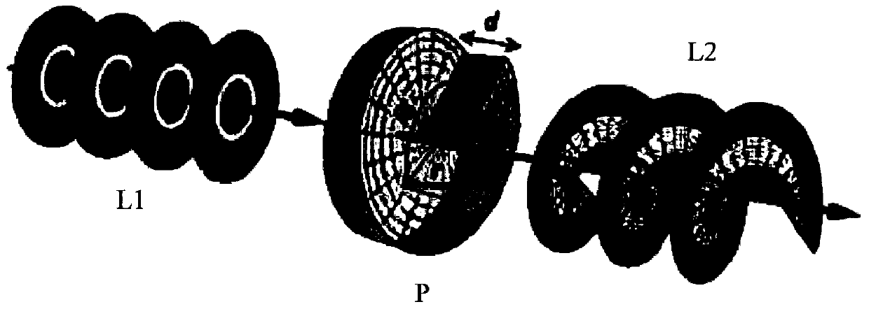
[0022] In order to further reduce the light spots of excited fluorescence, improve the resolution of the existing STED microscopic imaging system, and realize super-resolution microscopic imaging, the present invention provides a STED microscopic imaging system using radially polarized light beams. The radially polarized beam is a kind of polarized beam whose polarization state on the beam cross section has axisymmetric characteristics with respect to the beam propagation axis. As shown in Figure 1(a), the polarization state of the radially polarized beam at each local position on the cross section is linearly polarized, and its polarization direction is along the radial direction. By passing the radially polarized beam L1 through a vortex phase plate P to modulate the phase of the radially polarized b...


PUM


Abstract

A super-resolution STED micro imaging method based on a radially polarized vortex beam comprises the steps as follows: a stimulation beam is aligned, and a first parallel beam is obtained; the first parallel beam is converted into a first radially polarized beam; the first radially polarized beam is modulated and focused on a sample of a focal plane, and a focus solid light spot is obtained; a restraint beam is aligned, and a second parallel beam is obtained; the second parallel beam is converted into a second radially polarized beam; the second radially polarized beam is converted into the radially polarized vortex beam; the radially polarized vortex beam is modulated and focused on the sample of the focal plane, and a focus hollow light spot is obtained, wherein the center of the focus hollow spot and the center of the focus solid light spot are overlapped, so that only a middle point located in the middle position and having a size smaller than a diffraction limit emits fluorescence; and a detector detects the fluorescence emitted by the middle point.

Description

technical field [0001] The invention relates to stimulated emission loss microscopic imaging technology, in particular to a super-resolution stimulated emission loss microscopic imaging method and device using radially polarized vortex beams. Background technique [0002] The development of modern biology and material science has put forward higher and higher resolution requirements for the study of microstructure, hoping to reveal the physical essence of life processes and material properties from the molecular level. However, limited by the optical diffraction limit, the horizontal resolution of ordinary optical microscopes can only reach 200nm, and the vertical resolution is about 500nm, which is powerless for the study of subcellular and molecular structures. Although electron microscopy (Electron Microscopy), atomic force microscopy (Atom Force Microscopy), near-field scanning optical microscopy (Near-field Scanning Optical Microscope, NSOM) and other techniques can obt...

Claims


Application Information

Patent Timeline
IPC IPC(8): G02B21/06
Inventor 祝连庆周哲海郭阳宽董明利娄小平潘志康张荫民
Owner BEIJING INFORMATION SCI & TECH UNIV
Why Eureka
Try Eureka