Backlight device and liquid crystal display device

a liquid crystal display and backlight technology, applied in the direction of lighting and heating equipment, instruments, machines/engines, etc., can solve the problems of increasing the number of components, increasing the thickness and cost of the components, and increasing the complexity of the structure, etc., to achieve good visibility, excellent display quality, and high brightness

Inactive Publication Date: 2006-01-03
ALPS ALPINE CO LTD
View PDF8 Cites 60 Cited by
  • Summary
  • Abstract
  • Description
  • Claims
  • Application Information

AI Technical Summary

Benefits of technology

[0041]The liquid crystal display device of the present invention comprises the backlight device on the back surface of the liquid crystal display unit. Accordingly, it can uniformly and brightly illuminate the display area (illuminated area), and good visibility, high brightness and excellent display quality can be obtained. In addition, since the number of components can be reduced, the thin liquid crystal display device can be manufactured at low cost.

Problems solved by technology

Therefore, there are problems in that the number of components increase, the structure thereof becomes complicated, and the thickness and cost thereof increases.
In addition, in the prior art, a cheap thin backlight device which can uniformly and brightly illuminate the display area of the liquid crystal display unit 320 cannot be realize.
Further, since the conventional liquid crystal display device 300 comprises the above-mentioned backlight device 310, the thickness of the entire device increases and the cost thereof increase.

Method used


Image

  • Backlight device and liquid crystal display device
  • Backlight device and liquid crystal display device
  • Backlight device and liquid crystal display device

Examples


first embodiment

[0068](First Embodiment)

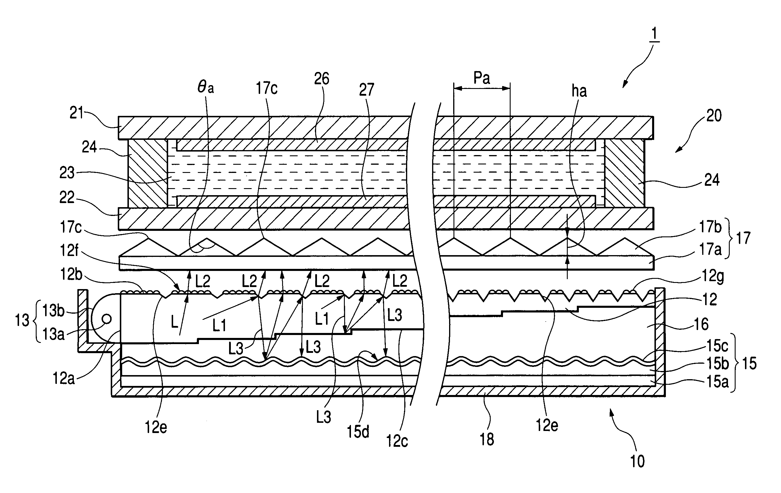
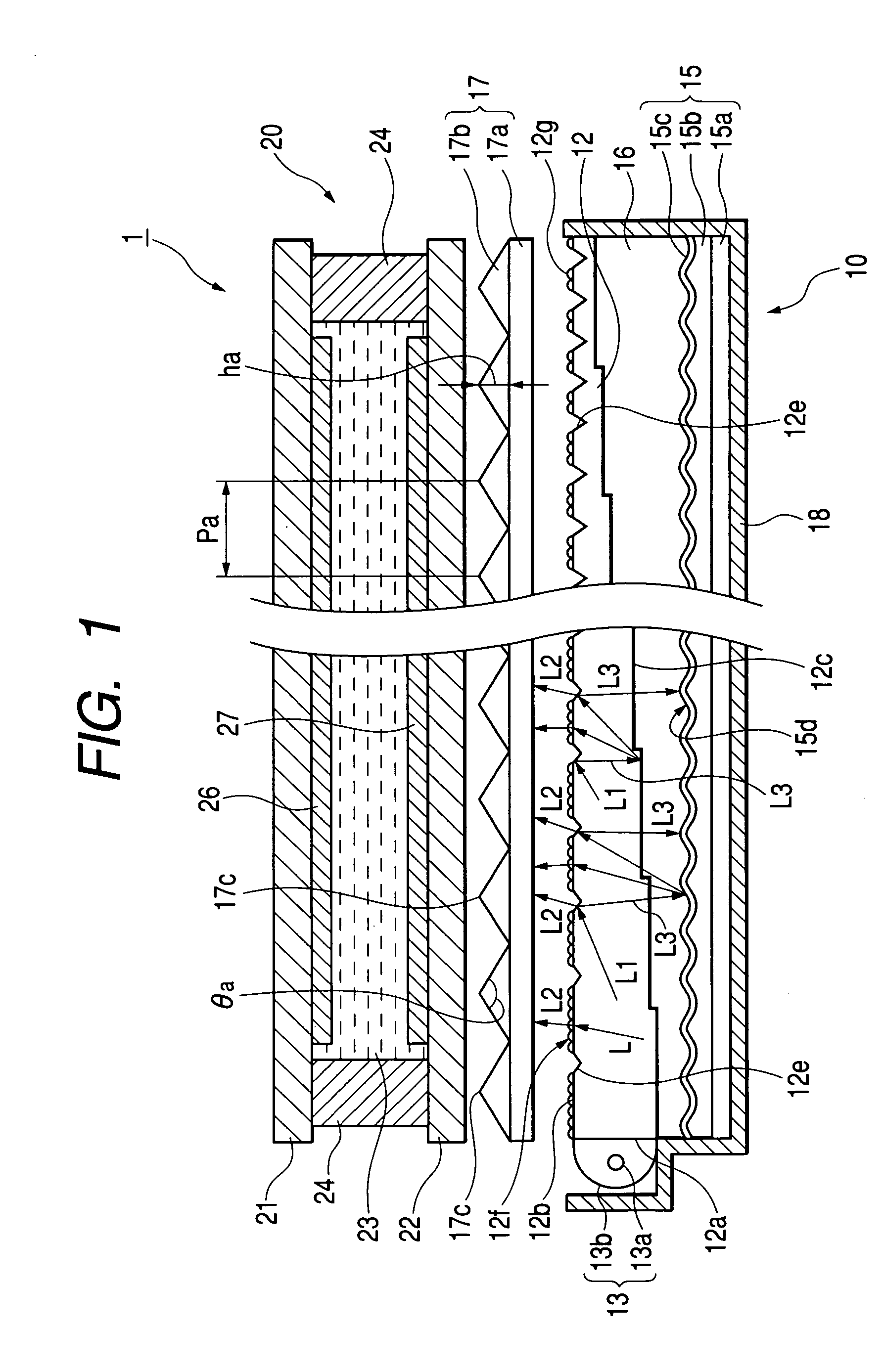
[0069]FIG. 1 is a cross sectional view of a liquid crystal display device having a backlight device (a back irradiating device) according to a first embodiment of the present invention.

[0070]The liquid crystal display device 1 according to this embodiment comprises a liquid crystal display unit 20, and a backlight device 10 positioned at the back surface of the liquid crystal display unit 20 for illuminating the liquid crystal display unit 20 at the back surface thereof.

[0071]The liquid crystal display unit 20 is a transmissive type and comprises a first substrate 21 and a second substrate 22 which are attached to each other as one body by sealing material 24. The first substrate 21 and the second substrate 22 are made of glass and face each other with a liquid crystal layer 23 sandwiched therebetween. Display circuits 26, 27 are formed on the liquid crystal layers 23 of the first substrate 21 and the second substrate 22, respectively.

[0072]The display circui...

second embodiment

[0129](Second Embodiment)

[0130]Next, the liquid crystal display device according to the second embodiment of the present invention will be explained with reference to FIG. 12. FIG. 12 is a cross sectional view of the liquid crystal display device according to the second embodiment.

[0131]The liquid crystal display device la according to the second embodiment is different from the liquid crystal display device 1 according to the first embodiment in the structure of the backlight device. That is, the backlight device 10a of this embodiment is provided with two prism sheets 48, 49 on the emitting surface 12b of the light guide plate 12. Since this embodiment has the same structure as the backlight device 10 of the first embodiment except for the above-mentioned structure, hereinafter, the detailed description thereof will be omitted. Also, since the basic structure of the liquid crystal display unit 20 is equal to that of the liquid crystal display unit shown in FIG. 1, the detailed des...

third embodiment

[0135](Third Embodiment)

[0136]Next, the liquid crystal display device according to the third embodiment of the present invention will be explained with reference to FIG. 13. FIG. 13 is a cross sectional view of the liquid crystal display device according to the third embodiment.

[0137]The liquid crystal display device 1b according to the third embodiment is different from the liquid crystal display device 1 according to the first embodiment in the structure of the backlight device. That is, the backlight device 10b of this embodiment is provided with a light diffusion sheet 14 on the lower surface of the light guide plate 12, instead of the diffusive reflector 15. Since this embodiment has the same structure as the backlight device 10 of the first embodiment except for the above-mentioned structure, hereinafter, the detailed description thereof will be omitted. Also, since the basic structure of the liquid crystal display unit 20 is equal to that of the liquid crystal display unit sh...


PUM

PropertyMeasurementUnit
angleaaaaaaaaaa
inclination angle θjaaaaaaaaaa

Abstract

A backlight device 10 wherein a light source 13 and a light guide plate 12 for introducing light components from the light source 13 from the incident surface 12a provided on an end surface to emit the light from the surface 12b are included, a plurality of the wedge-shaped grooves 12e are formed on the surface 12b of the light guide plate 12 in stripes in plan view, and micro-irregularities 12g are formed between adjacent wedge-shaped grooves 12e is disclosed. A liquid crystal display device 1 having the backlight device 10 formed on the back surface of the liquid crystal display unit 20 is disclosed.

Description

[0001]This application claims the benefit of priority to Japanese Patent Application No. 2002-355747, herein incorporated by reference.BACKGROUND OF THE INVENTION[0002]1. Field of the Invention[0003]The present invention relates to a backlight device being suitable for backlight for a liquid crystal display device and a liquid crystal display device having the same.[0004]2. Description of the Related Art[0005]FIG. 24 is a schematic cross sectional view showing an example of a conventional passive-type (a simple matrix type) liquid crystal display device. The liquid crystal display device 300 according to this example comprises a transmissive or transflective liquid crystal display unit 320 and a backlight device 310 disposed on the back surface of the liquid crystal display unit 320 (refer to Patent Documents 1 and 2).[0006]The backlight device 310 is configured so that the light from an elongate light source 313 such as a Cold Cathode Florescent Lamp (CCFL) is introduced to an inci...

Claims


Application Information

Patent Timeline
Patent Type & Authority Patents(United States)
IPC IPC(8): F21V7/04F21V8/00G02B6/00F21Y101/02F21Y103/00G02B5/02G02F1/13357
CPCG02B6/0036G02B6/0038G02B6/0053G02B6/0048
Inventor NAGAKUBO, HIDEAKIYAMAMOTO, KOICHI
Owner ALPS ALPINE CO LTD
Why Eureka
Try Eureka