Multiple-nozzle thermal evaporation source

a thermal evaporation source and multi-nozzle technology, applied in vacuum evaporation coating, sublimation, separation processes, etc., can solve the problem of requiring a significant quantity of heat shielding

Inactive Publication Date: 2006-01-03
UNIVERSITY OF DELAWARE
View PDF5 Cites 43 Cited by
  • Summary
  • Abstract
  • Description
  • Claims
  • Application Information

AI Technical Summary

Problems solved by technology

These sources require a signifi

Method used


Image

  • Multiple-nozzle thermal evaporation source
  • Multiple-nozzle thermal evaporation source
  • Multiple-nozzle thermal evaporation source

Examples


Embodiment Construction

[0012]The present invention relates to improvements in multiple nozzle thermal evaporation source techniques. A known approach is described in U.S. Pat. No. 4,325,986, all of the details of which are incorporated herein by reference thereto.

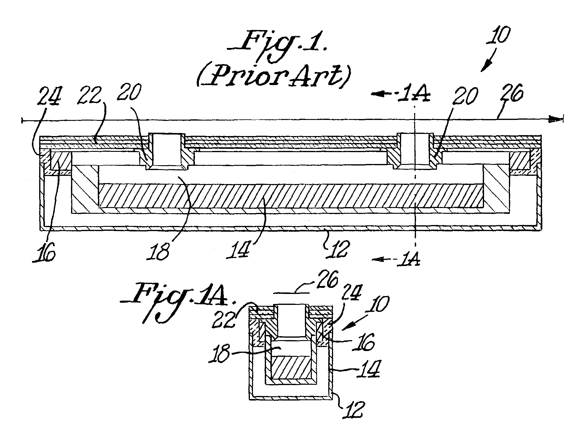
[0013]FIGS. 1 and 1A illustrate a prior art multiple nozzle thermal evaporation source 10 which includes a containment box 12 in which is located an evaporation chamber 18 containing a deposition source 14. Suitable heating structure 16 is also provided in containment box 12. The deposition source 14 is located below nozzles 20 which extend through suitable heat shielding 22. Containment box 12 is also provided with suitable insulation 24. A continuous semi-conductor film substrate 26 passes over the nozzles 20.

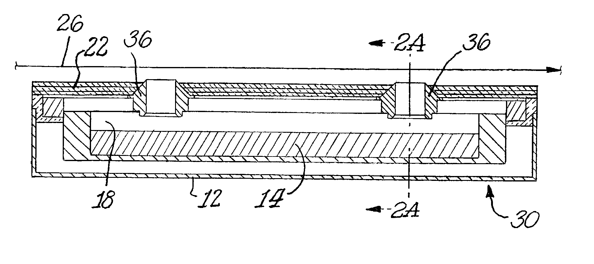
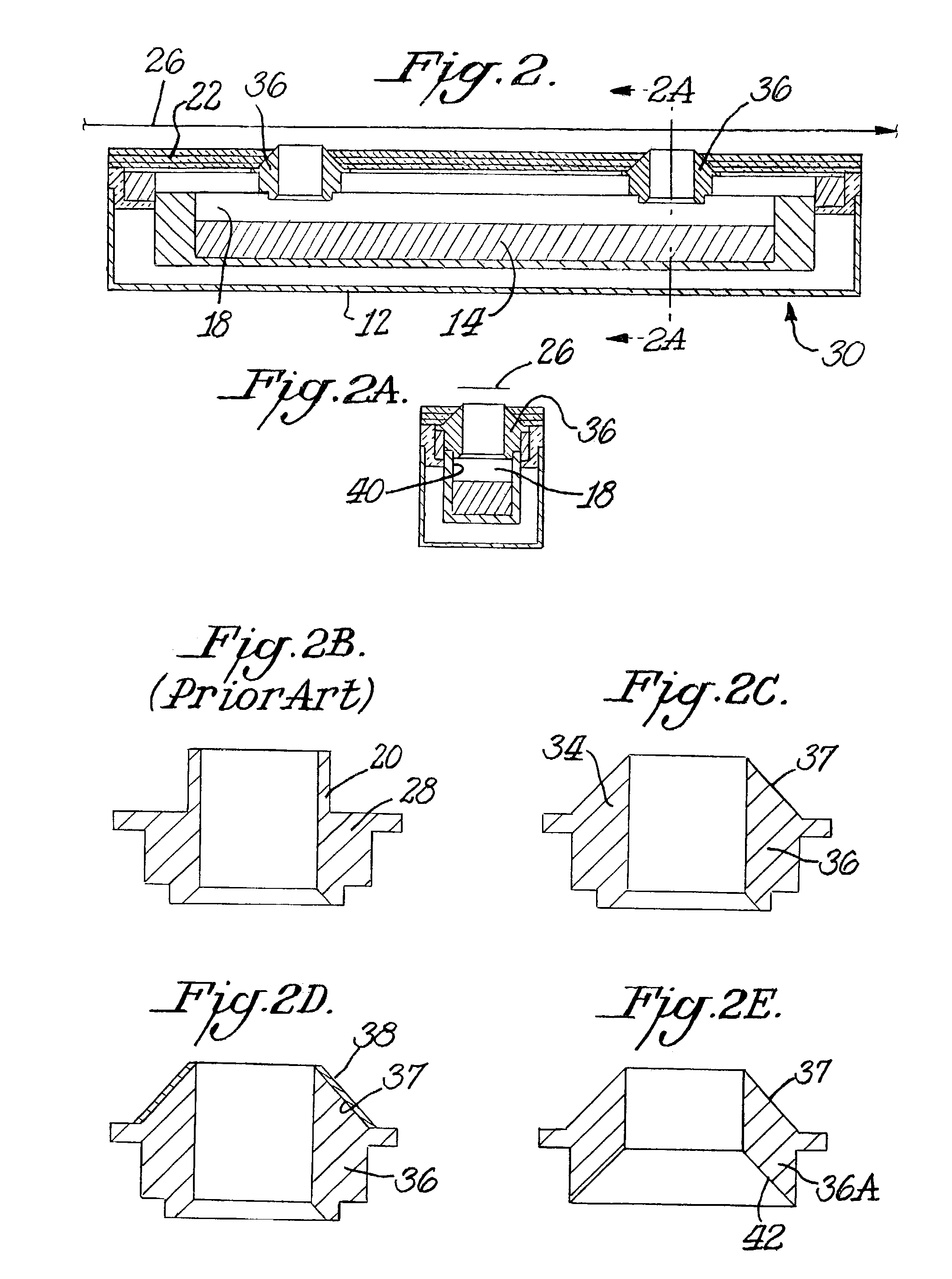
[0014]FIG. 2 shows a multiple nozzle thermal evaporation source 30 in accordance with this invention. Source 30 contains many of the same components as the prior art source shown in FIG. 10. Accordingly, like numerals are used for like par...


PUM

PropertyMeasurementUnit
Temperatureaaaaaaaaaa
Shapeaaaaaaaaaa
Electrical conductoraaaaaaaaaa

Abstract

A multiple nozzle thermal evaporation source includes a plurality of nozzles having a tapered shape. The nozzles may comprise a thermally conductive material having a low emissivity material.

Description

CROSS-REFERENCE TO RELATED APPLICATION[0001]This application is a divisional of Ser. No. 10 / 234,604, filed Sep. 4, 2002 which is based upon provisional application Ser. No. 60 / 322,039, filed Sep. 14, 2001.BACKGROUND OF THE INVENTION[0002]The invention relates to deposition techniques involving thermal evaporation. In general, such techniques are used, for example, in the production of thin-film solar cells which requires large-area deposition techniques. Known techniques include roll coating by thermal evaporation in which a semiconductor film is deposited on a wide flexible substrate continuously drawn over an array of thermal evaporation sources. These sources require a significant quantity of heat shielding. The only elements of the source not covered by such heat shielding are the effusion nozzles wherein the nozzle tip extends beyond the outermost surface of the heat shielding.[0003]U.S. Pat. No. 4,325,986 discloses work by others in this field.SUMMARY OF THE INVENTION[0004]An ...

Claims


Application Information

Patent Timeline
IPC IPC(8): C23C14/24
CPCC23C14/243
Inventor ESER, ERTENHANKET, GREGORY M.
Owner UNIVERSITY OF DELAWARE
Why Eureka
Try Eureka