Pattern compensation for stitching

a pattern compensation and stitching technology, applied in the field of stitching techniques, can solve the problems of generating retention time problems, discontinuities in lines, and difficulty in increasing resolution and field size at the same tim

Inactive Publication Date: 2006-01-03
TAIWAN SEMICON MFG CO LTD
View PDF10 Cites 54 Cited by
  • Summary
  • Abstract
  • Description
  • Claims
  • Application Information

AI Technical Summary

Benefits of technology

[0012]A method for transferring a pattern from a mask to a substrate (or wafer), comprises dividing a mask generation data file into a plurality of segments. The segments include a main pattern area and a stitching area. Each stitching area contains a respective common pattern. An image of an illuminated portion of the main pattern area is formed. Connection ends of the segments in a substrate area (or wafer area) are illuminated with an illumination beam. An image of the illuminated portion of the main pattern area is formed, and a halftone gray level dosage distribution is produced in the substrate area (or wafer area) corresponding to the common pattern. The common patterns of adjacent segments substantially overlap in the substrate area (or wafer area).
[0011]A method of fabricating a mask comprises: dividing a mask generation date file into a plurality of segments, said segments including a main pattern area and a stitching area, said each stitching area containing a respective geometric pattern; and forming a set of geometric features in the stitching area, said geometric features producing a halftone gray level dosage distribution after illumination.

Problems solved by technology

It is difficult to increase resolution and increase the field size at the same time.
If there are positional errors in registering the corresponding subfields, the result is discontinuities in the line.
Stitching errors can cause leakage or generate retention time problems, if the narrowest line width in the stitching area is less than 90% of the gate length.
Stitching errors can also produce a weaker device in terms of drive current, if the widest line width in the stitching area is too large.

Method used


Image

  • Pattern compensation for stitching
  • Pattern compensation for stitching
  • Pattern compensation for stitching

Examples


Embodiment Construction

[0023]This description of the exemplary embodiments is intended to be read in connection with the accompanying drawings, which are to be considered part of the entire written description. In the description, relative terms such as “lower,”“upper,”“horizontal,”“vertical,”“above,”“below,”“up,”“down,”“top” and “bottom” as well as derivative thereof (e.g., “horizontally,”“downwardly,”“upwardly,” etc.) should be construed to refer to the orientation as then described or as shown in the drawing under discussion. These relative terms are for convenience of description and do not require that the apparatus be constructed or operated in a particular orientation.

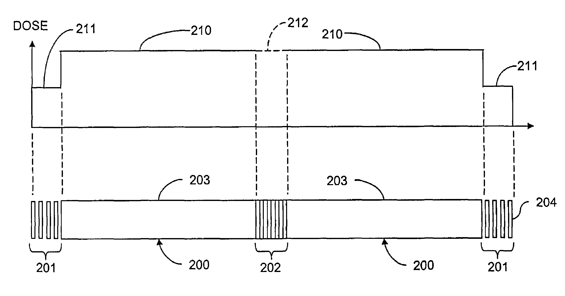
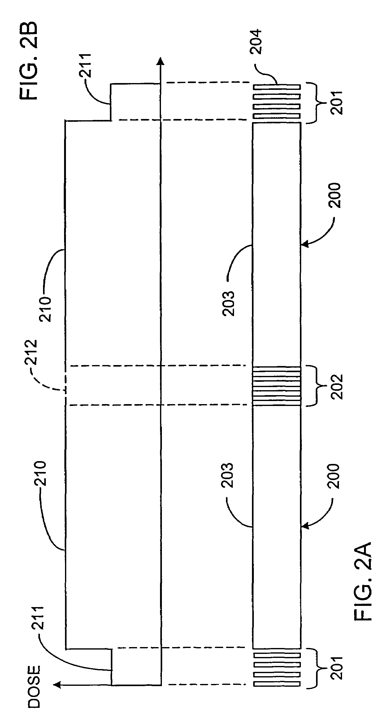
[0024]FIG. 2 shows an exemplary structure and method for transferring a pattern from a mask to a substrate (or wafer).

[0025]A mask generation data file is divided into a plurality of segments 200, such that each segment can fit within the maximum field size for the projection optics of the stepper system. The segments 200 include a ma...


PUM

PropertyMeasurementUnit
widthaaaaaaaaaa
areaaaaaaaaaaa
line widthsaaaaaaaaaa

Abstract

A method for transferring a pattern from a mask to a substrate (or wafer), comprises dividing a mask generation data file into a plurality of segments. The segments include a main pattern area and a stitching area. Each stitching area contains a respective common pattern. An image of an illuminated portion of the main pattern area is formed. Connection ends of the segments in a substrate area (or wafer area) are illuminated with an illumination beam. An image of the illuminated portion of the main pattern area is formed, and a halftone gray level dosage distribution is produced in the substrate area (or wafer area) corresponding to the common pattern. The common patterns of adjacent segments substantially overlap in the substrate area (or wafer area).

Description

FIELD OF THE INVENTION[0001]The present invention relates generally to semiconductor fabrication techniques, and more specifically to stitching techniques.BACKGROUND[0002]The semiconductor fabrication industry continuously strives to reduce geometries to allow greater numbers of devices to be formed within an integrated circuit (IC). There are competing requirements to form larger masks with finer line widths. It is difficult to increase resolution and increase the field size at the same time.[0003]An illumination beam exposure system includes an illumination optical system to illuminate a mask with an illumination beam, and a projection optical system to project the illumination beam through a mask onto a sensitive substrate. For the critical dimension (CD) to be small, a high degree of controllability is required for the electron beam and pattern placement. In direct write electron beam exposure systems, for any given number of address points in the mask definition, as the spacing...

Claims


Application Information

Patent Timeline
Patent Type & Authority Patents(United States)
IPC IPC(8): G03F9/00G03F7/20G03B27/42G03F1/00G03F1/20G03F1/36
CPCG03B27/42G03F1/144G03F7/70475G03F1/36G03F1/20G03F1/00
Inventor CHANG, CHUNG-HSINGLIN, CHIEN-HUNGLIN, BURN J.LIN, CHIA-HUICHIN, CHIH-CHENGLIN, CHIN-HSIANGLIANG, FU-JYECHEN, JENG-HORNGHO, BANG-CHING
Owner TAIWAN SEMICON MFG CO LTD
Why Eureka
Try Eureka