Transformer coupled oscillator and method

a technology of transformer coupled oscillators and oscillators, which is applied in the direction of pulse generators, pulse techniques, automatic frequency control details, etc., can solve the problem of disadvantage in adding such active circuitry

Inactive Publication Date: 2006-01-03
APPLE INC
View PDF7 Cites 41 Cited by
  • Summary
  • Abstract
  • Description
  • Claims
  • Application Information

AI Technical Summary

Problems solved by technology

The requirement to add such active circuitry is a disadvantage due to consumption of current and space.

Method used


Image

  • Transformer coupled oscillator and method
  • Transformer coupled oscillator and method
  • Transformer coupled oscillator and method

Examples


Embodiment Construction

)

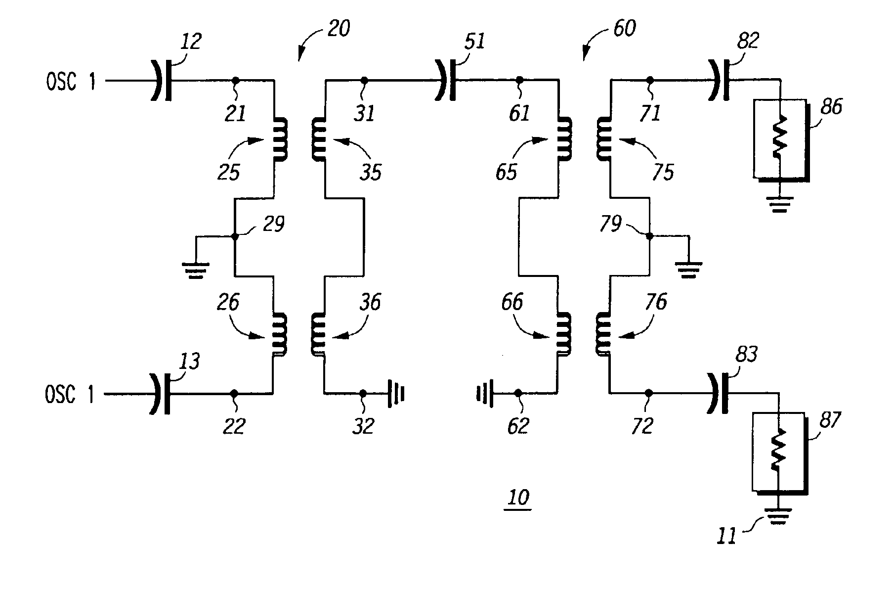
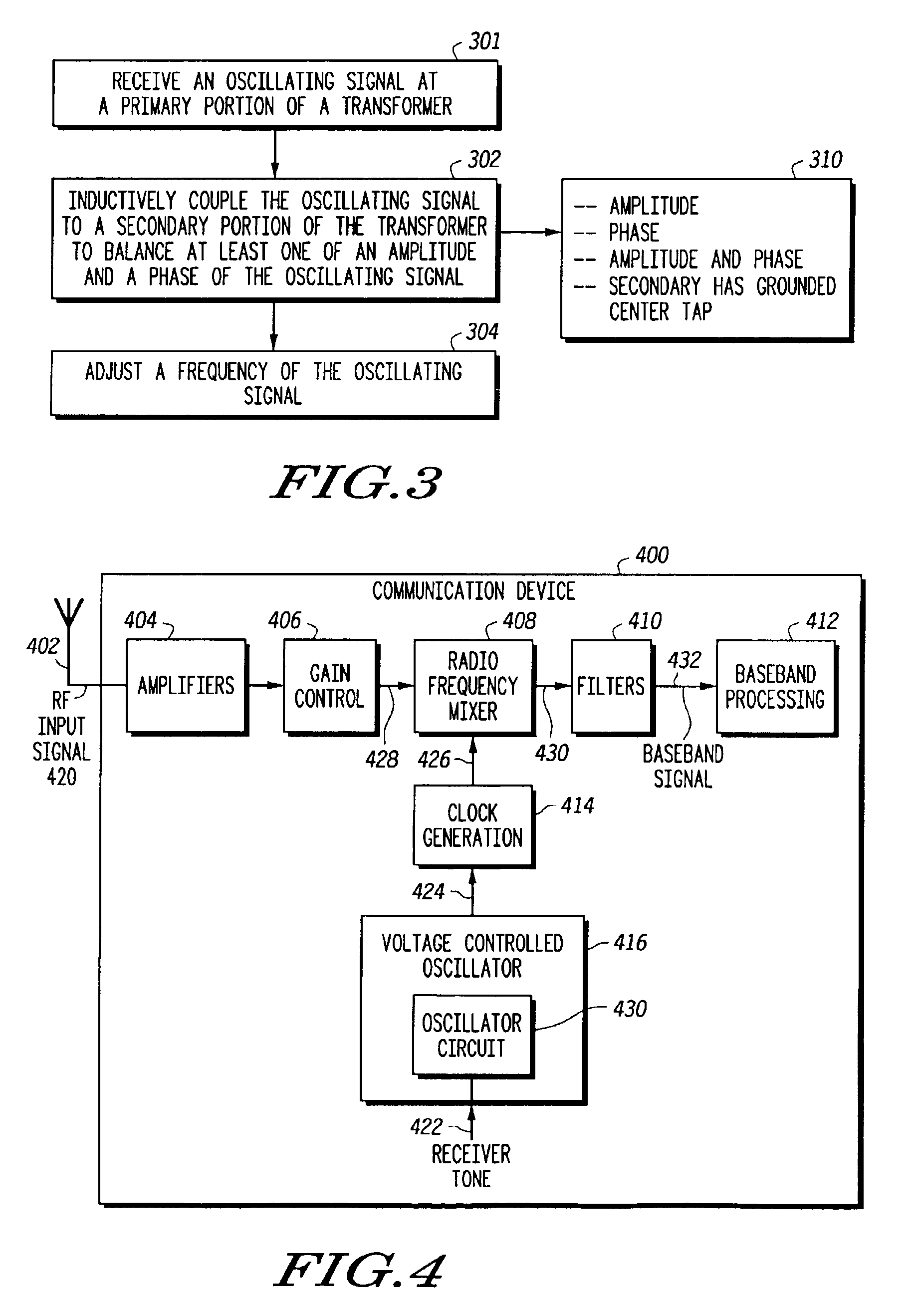
[0011]In a particular embodiment, an oscillator adjustment circuit is disclosed. The oscillator adjustment circuit includes a primary coil of a transformer forming at least a portion of an oscillator element. The oscillator adjustment circuit further includes a secondary coil of the transformer. The secondary coil has an offset grounded center tap.

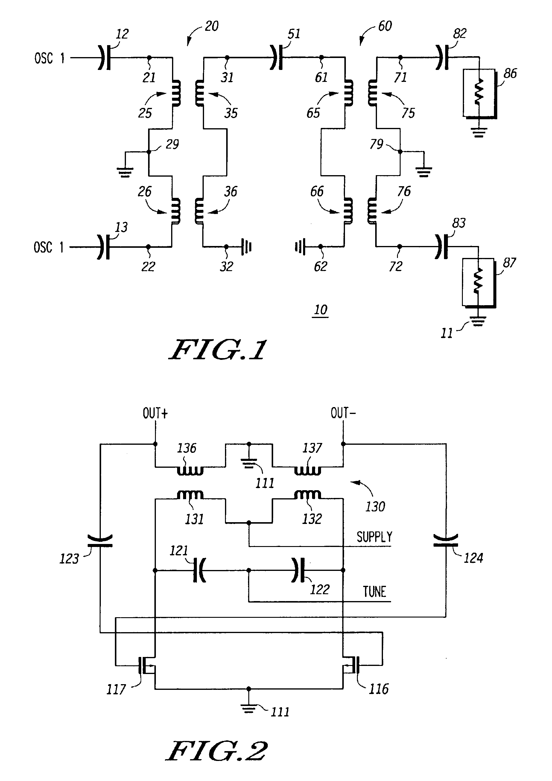
[0012]Referring to FIG. 1, an oscillator adjustment circuit 10 is illustrated. The oscillator adjustment circuit 10 has a first transformer 20 and a second transformer 60. The first transformer 20 has a primary coil that includes a first portion 25, a second portion 26, and a primary coil center tap 29 that is grounded. The first transformer 20 also includes a secondary coil which has a first portion 35, a second portion 36, and a center tap. The first transformer 20 has primary transformer terminals 21 and 22 and secondary transformer terminals 31 and 32. The first transformer 20 is responsive to an oscillator signal that is fed to a fir...


PUM


Abstract

In a particular embodiment, an oscillator adjustment circuit is disclosed. The oscillator adjustment circuit includes a resonator portion comprising a capacitive element coupled to an inductive element and a signal balancing portion comprising a secondary coil of the transformer. The inductive element comprises a primary coil of a transformer. The secondary coil has a grounded center tap.

Description

BACKGROUND[0001]1. Field of the Disclosure[0002]The present disclosure relates generally to oscillator adjustment circuits and related methods.[0003]2. Description of the Related Art[0004]In communication device receivers, oscillation circuits, such as a conventional voltage controlled oscillator (VCO), are commonly used. Certain oscillation circuits provide a differential output that may be corrected using a dedicated active circuit, such as a feedback amplifier. The requirement to add such active circuitry is a disadvantage due to consumption of current and space. Reduced space and current consumption is at a premium for mobile devices, such as cell phones and similar handsets.[0005]Accordingly, an improved oscillator circuit and method is desirable and would be useful.BRIEF DESCRIPTION OF THE DRAWINGS[0006]FIG. 1 is a circuit diagram that illustrates an embodiment of an oscillator including an oscillation adjustment circuit.[0007]FIG. 2 is a circuit diagram that illustrates an em...

Claims


Application Information

Patent Timeline
Patent Type & Authority Patents(United States)
IPC IPC(8): H03B5/00H03B5/12
CPCH03B5/1228H03B5/1212H03B5/1256H03B5/124H03B5/1296
Inventor MONDAL, JYOTICALANCA, NEILCUI, YANGOLAT, JOSEPH
Owner APPLE INC
Why Eureka
Try Eureka