Method and apparatus for reducing leakage power in a cache memory by using a timer control signal that removes power to associated cache lines

a cache memory and power dissipation technology, applied in the direction of memory adressing/allocation/relocation, instruments, liquid/fluent solid measurement, etc., can solve the problem that leakage power is expected to become a significant factor in the total power dissipation of the chip, and achieve the effect of reducing power consumption, reducing leakage power dissipation, and reducing leakage power

Inactive Publication Date: 2006-01-03
BROADCOM INT PTE LTD
View PDF20 Cites 13 Cited by
  • Summary
  • Abstract
  • Description
  • Claims
  • Application Information

AI Technical Summary

Benefits of technology

[0007]Generally, a method and apparatus are disclosed for reducing leakage power in a cache memory. The present invention removes power from cache lines that have been inactive for some period of time assuming that these cache lines are unlikely to be accessed in the future. A cache decay technique is employed that removes power from cache lines that have not been accessed for a predefined time interval, referred to as the decay interval. The cache decay techniques disclosed herein reduce leakage power dissipation in cache memories and thus yield cache memories with reduced power consumption. The cache-line granularity of the present invention permits a significant reduction in leakage power while at the same time preserving much of the performance of the cache. The cache decay techniques of the present invention can be successfully applied to both data and instruction caches, to set-associative caches and to multilevel cache hierarchies.

Problems solved by technology

Since chip transistor counts continue to increase, and every transistor that has power applied will leak irrespective of its switching activity, leakage power is expected to become a significant factor in the total power dissipation of a chip.

Method used


Image

  • Method and apparatus for reducing leakage power in a cache memory by using a timer control signal that removes power to associated cache lines
  • Method and apparatus for reducing leakage power in a cache memory by using a timer control signal that removes power to associated cache lines
  • Method and apparatus for reducing leakage power in a cache memory by using a timer control signal that removes power to associated cache lines

Examples


Embodiment Construction

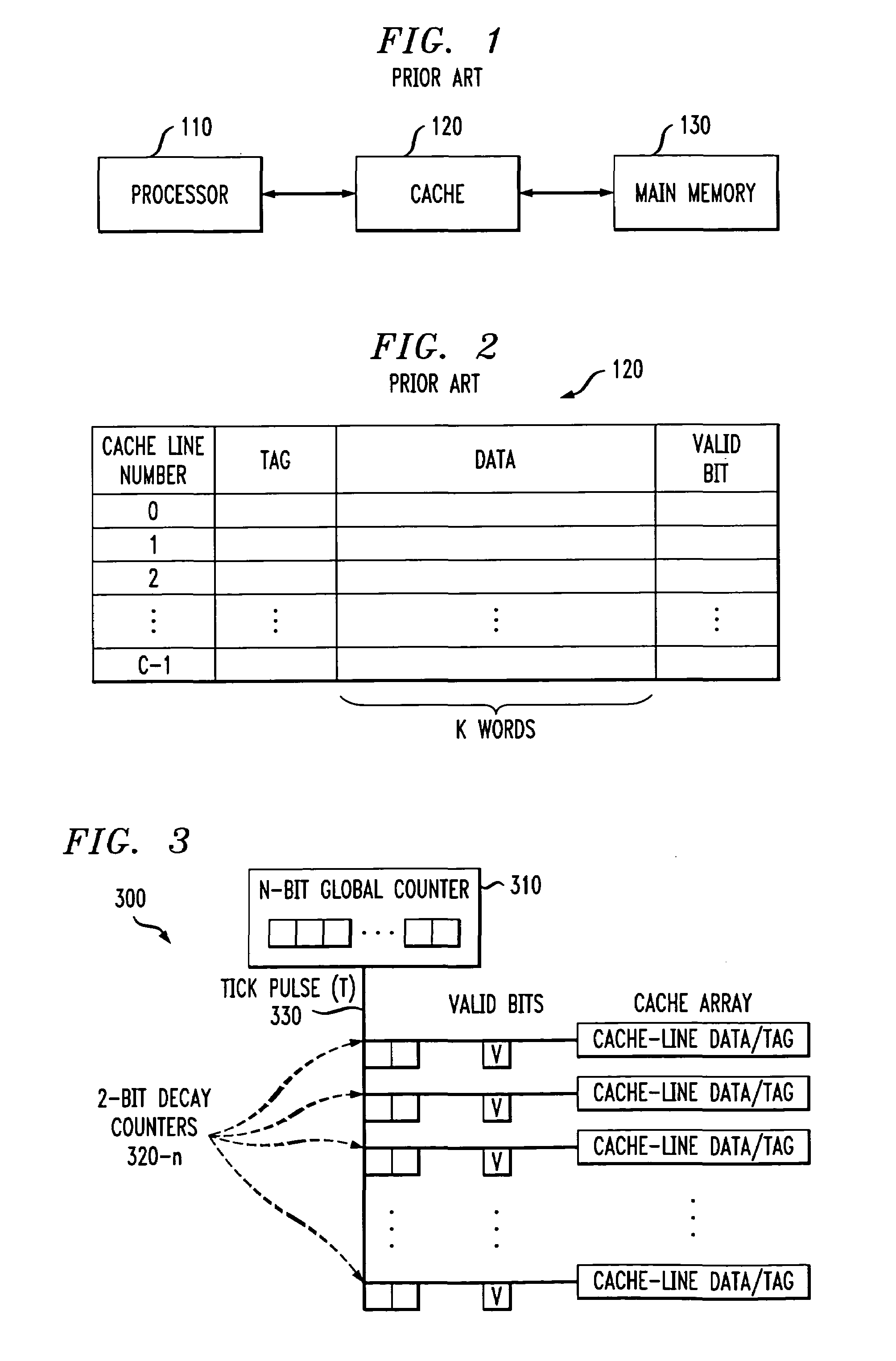
[0020]FIG. 2 illustrates the structure of the conventional cache memory 120 of FIG. 1 in further detail. As shown in FIG. 2, the cache memory 120 consists of C cache lines of K words each. The number of lines in the cache memory 120 is generally considerably less than the number of blocks in main memory 130. At any time, a portion of the blocks of main memory 130 resides in lines of the cache memory 120. An individual line in the cache memory 120 cannot be uniquely dedicated to a particular block of the main memory 130. Thus, as shown in FIG. 2, each cache line includes a tag indicating which particular block of main memory 130 is currently stored in the cache 120. In addition, each cache line includes a valid bit indicating whether the stored data is valid.

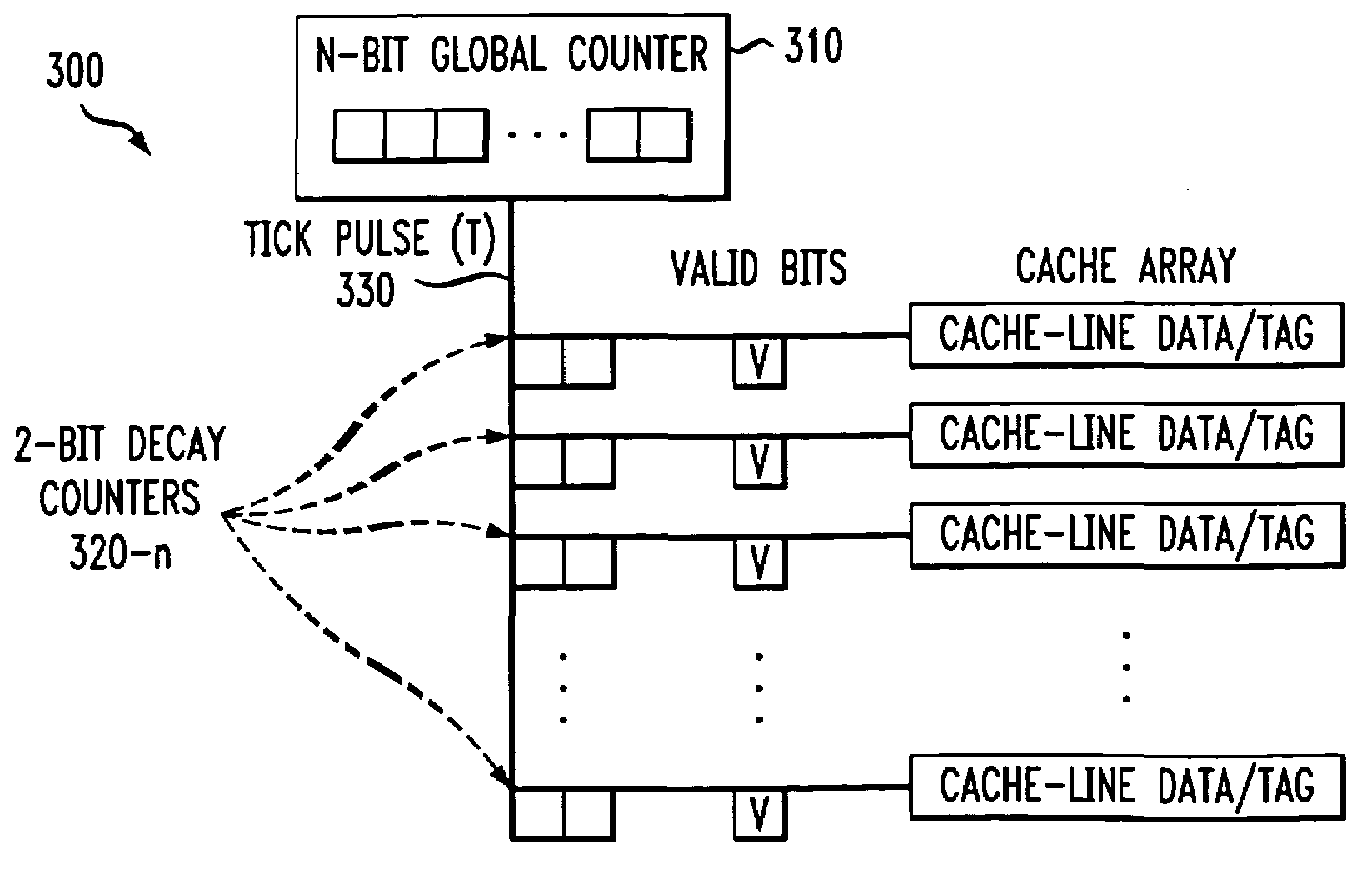
[0021]The present invention provides a cache decay technique that removes power from cache lines that have not been accessed for a predefined time interval, referred to as the decay interval. The decay interval may be variable to...


PUM


Abstract

A method and apparatus are disclosed for reducing leakage power in a cache memory. A cache decay technique is employed for both data and instruction caches that removes power from cache lines that have not been accessed for a predefined time interval, referred to as the decay interval. The cache-line granularity of the present invention permits a significant reduction in leakage power while at the same time preserving much of the performance of the cache. The decay interval is maintained using a timer that is reset each time the corresponding cache line is accessed. The decay interval may be fixed or variable. Once the decay interval timer exceeds a specified decay interval, power to the cache line is removed. Once power to the cache line is removed, the contents of the data and tag fields are allowed to decay and the valid bit associated with the cache line is reset. When a cache line is later accessed after being powered down by the present invention, a cache miss is incurred while the cache line is again powered up and the data is obtained from the next level of the memory hierarchy.

Description

CROSS-REFERENCE TO RELATED APPLICATION[0001]This application claims the benefit of U.S. Provisional Application No. 60 / 243,173, filed Oct. 25, 2000.FIELD OF THE INVENTION[0002]The present invention relates generally to cache memory devices, and more particularly, to methods and apparatus for reducing the leakage power in such cache memories.BACKGROUND OF THE INVENTION[0003]Cache memories reduce memory access times of large external memories. FIG. 1 illustrates a conventional cache architecture where a cache memory 120 is inserted between one or more processors 110 and a main memory 130. Generally, the main memory 130 is relatively large and slow compared to the cache memory 120. The cache memory 120 contains a copy of portions of the main memory 130. When the processor 110 attempts to read an area of memory, a check is performed to determine if the memory contents are already in the cache memory 120. If the memory contents are in the cache memory 120 (a cache “hit”), the contents ar...

Claims


Application Information

Patent Timeline
Patent Type & Authority Patents(United States)
IPC IPC(8): G06F1/32G06F12/08G11C5/14G11C11/401G11C11/406G11C11/417
CPCG11C11/417G11C5/143
Inventor KAXIRAS, STEFANOSDIODATO, PHILIP W.MCLELLAN, JR., HUBERT RAENARLIKAR, GIRIJA
Owner BROADCOM INT PTE LTD
Why Eureka
Try Eureka