Method and system of dynamic power cutoff for active leakage reduction in circuits

a technology of active leakage and circuit, applied in the direction of power consumption reduction, pulse technique, instruments, etc., can solve the problems of long sleep period, data loss, and reduced circuit leakage power in standby mode, so as to reduce active leakage

Inactive Publication Date: 2010-10-05
BUSHNELL MICHAEL +1
View PDF4 Cites 11 Cited by
  • Summary
  • Abstract
  • Description
  • Claims
  • Application Information

AI Technical Summary

Benefits of technology

[0009]The present invention relates to a novel active leakage power reduction technique, referred to as the dynamic power cutoff technique (DPCT). The DPCT method of the present invention can reduce active leakage, standby leakage, and dynamic power by applying the dynamic power cutoff technique to a circuit.
[0010]In the method and system for dynamic power cutoff for active leakage reduction in circuits of the present invention, a switching window is determined for each gate, during which a gate makes its transitions. For example, the switching window can be determined by static timing analysis. Then, the circuit is optimally partitioned into different groups based on the minimal switching window (MSW) of each gate. Finally, power cutoff transistors are inserted into each group to control the power connections of that group. Each group is turned on only long enough for a wavefront of changing signals to propagate through that group. Since each gate is only turned on during a small timing window within each clock cycle, this significantly reduces active leakage power.
[0011]Instead of finding the idle circuit part by conventional Shannon expansion, the present invention identifies when a gate is idle from its switching window, the timing window during which the gate makes its transition within each clock cycle. Active leakage power is saved by turning on the power connections of each gate only within its switching window during each clock cycle. Standby leakage can also be reduced by turning off the power connections of all gates all of the time once the circuit is idle. The technique of the present invention also reduces dynamic power by reducing the circuit glitches. Results on ISCAS '85 benchmark circuits modeled using 70 nm Berkeley Predictive Models [1] show up to 90% active leakage, 99% standby leakage, 54% dynamic power, and 72% total power savings.

Problems solved by technology

One limitation is that data can be lost during the long sleep period due to the collapsed virtual VDD signal.
One common shortcoming of the above-described techniques is that they can only reduce the circuit leakage power in standby mode.
However, this technique does not reduce the leakage on critical paths.
Thus, it is it not advantageous for practical circuits, whose paths are usually well balanced.

Method used


Image

  • Method and system of dynamic power cutoff for active leakage reduction in circuits
  • Method and system of dynamic power cutoff for active leakage reduction in circuits
  • Method and system of dynamic power cutoff for active leakage reduction in circuits

Examples


Embodiment Construction

[0020]Reference will now be made in greater detail to a preferred embodiment of the invention, an example of which is illustrated in the accompanying drawings. Wherever possible, the same reference numerals will be used throughout the drawings and the description to refer to the same or like parts.

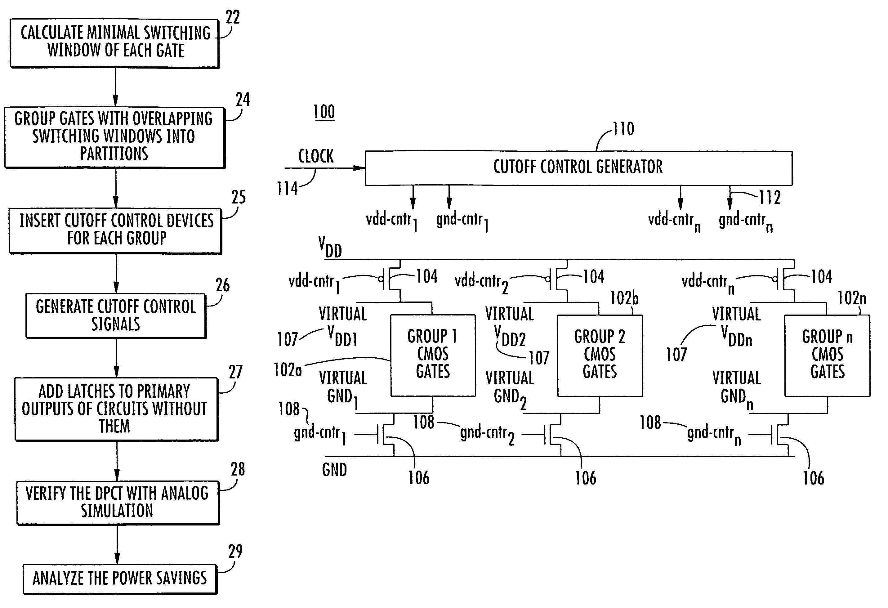
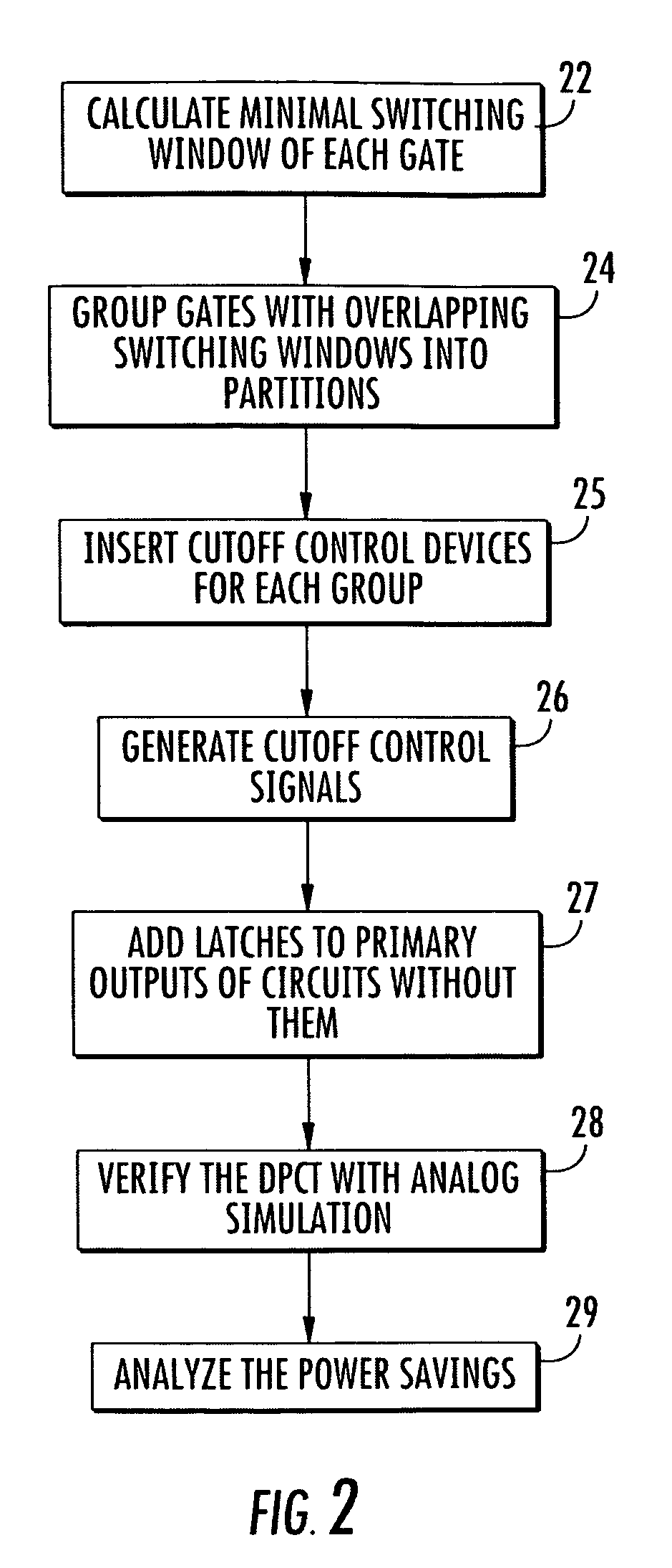
[0021]FIG. 2 is a flow diagram of a method for dynamic power cutoff for active leakage reduction in a circuit 20 in accordance with the teachings of the present invention. In block 22, a minimal switching window (MSW) for each gate is identified. In one embodiment, static timing analysis can be used to determine the minimal switching window (MSW).

[0022]The switching window and minimal switching window (MSW) of a gate are based on a timing window, as shown in FIG. 3. The timing window can be conventional as described in T. Raja, V. Agrawal, and M. Bushnell, “CMOS Circuit Design for Minimum Dynamic Power and Highest Speed,” in Proc. of the 17th Int'l. Conf on VLSI Design, pp. 1035-1040, Janu...


PUM


Abstract

The present invention relates to a novel active leakage power reduction technique, referred to as the dynamic power cutoff technique (DPCT). The DPCT method of the present invention can reduce active leakage, standby leakage, and dynamic power by applying the dynamic power cutoff technique to a circuit. In the method and system for dynamic power cutoff for active leakage reduction in circuits of the present invention, a switching window is determined for each gate, during which a gate makes its transitions. For example, the switching window can be determined by static timing analysis. Then, the circuit is optimally partitioned into different groups based on the minimal switching window (MSW) of each gate. Finally, power cutoff transistors are inserted into each group to control the power connections of that group. Each group is turned on only long enough for a wavefront of changing signals to propagate through that group. Since each gate is only turned on during a small timing window within each clock cycle, this significantly reduces active leakage power.

Description

CROSS REFERENCE TO RELATED APPLICATION[0001]This application claims the benefit of U.S. Provisional Patent Application No. 60 / 849,539, filed Oct. 4, 2006, the entirety of which is hereby incorporated by reference into this application.BACKGROUND OF THE INVENTION[0002]1. Field of the Invention[0003]The present invention relates to reducing active leakage power in computer hardware and in particular to a method and system for active leakage power reduction in circuits using a dynamic power cutoff technique.[0004]2. Description of Related Art[0005]Leakage power is increasingly significant in CMOS circuits due to the exponential increase of subthreshold and gate leakage currents from technology scaling. Leakage power is becoming a major fraction of total VLSI chip power in active mode. Conventional leakage reduction techniques have been proposed. A forced stacking method reduces leakage power by inserting an extra serially connected transistor in the gate pulldown or pullup path and tur...

Claims


Application Information

Patent Timeline
Patent Type & Authority Patents(United States)
IPC IPC(8): G06F17/50
CPCH03K19/0016G06F1/3287G06F1/3203Y02B60/1282H03K2217/0036Y02B60/1278Y02D10/00
Inventor BUSHNELL, MICHAELYU, BAOZHEN
Owner BUSHNELL MICHAEL
Why Eureka
Try Eureka