
Compliant, ortho-planar, linear motion spring

a technology of linear motion and springs, applied in the field of springs, can solve the problems of wear and vibration of both parts, requiring some rotation during the operation of anything fixed to the surface of the platform, and requiring the rotation of the platform with the platform

Inactive Publication Date: 2006-01-10
BRIGHAM YOUNG UNIV
View PDF24 Cites 59 Cited by
  • Summary
  • Abstract
  • Description
  • Claims
  • Application Information

AI Technical Summary

Benefits of technology

[0016]The connecting structure has one or more sets of flexible and resilient members, each set being coupled in series between the base and platform. Each set includes at lea...

Problems solved by technology

One of the disadvantages of the prior art, like the spider and volute springs, is that they require some rotation to occur during their operation.
One disadvantage of rotation is that anything fixed to the surface of the platform will be required to rotate with the platform.
Second, if the platform is not fixed to the adjacent part, then the two components are left to slide against each other, causing wear to both parts as well as vibration and noise.
The abrasion also causes particle generation which can be a problem in many environments, such as in pneumatic positioners with small nozzels, or cleanrooms used for microelectronics fabrication.
Another problem with rotation is that if the platform shape is not circular, a rotating platform may require more clearance in order to avoid contact with nearby structures.
One final disadvantage is that rotation in the spider spring legs adds torsional stresses to the members.
The assembly tolerances are also required to be quite tight, increasing the cost of the assembly.
One disadvantage is that baffles are typically positioned at an angle, causing potential hysteresis and repeatability problems.

Method used


Image

  • Compliant, ortho-planar, linear motion spring
  • Compliant, ortho-planar, linear motion spring
  • Compliant, ortho-planar, linear motion spring

Examples


Embodiment Construction

[0056]For the purposes of promoting an understanding of the principles in accordance with the invention, reference will now be made to the embodiments illustrated in the drawings and specific language will be used to describe the same. It will nevertheless be understood that no limitation of the scope of the invention is thereby intended. Any alterations and further modifications of the inventive features illustrated herein, and any additional applications of the principles of the invention as illustrated herein, which would normally occur to one skilled in the relevant art and having possession of this disclosure, are to be considered within the scope of the invention claimed.

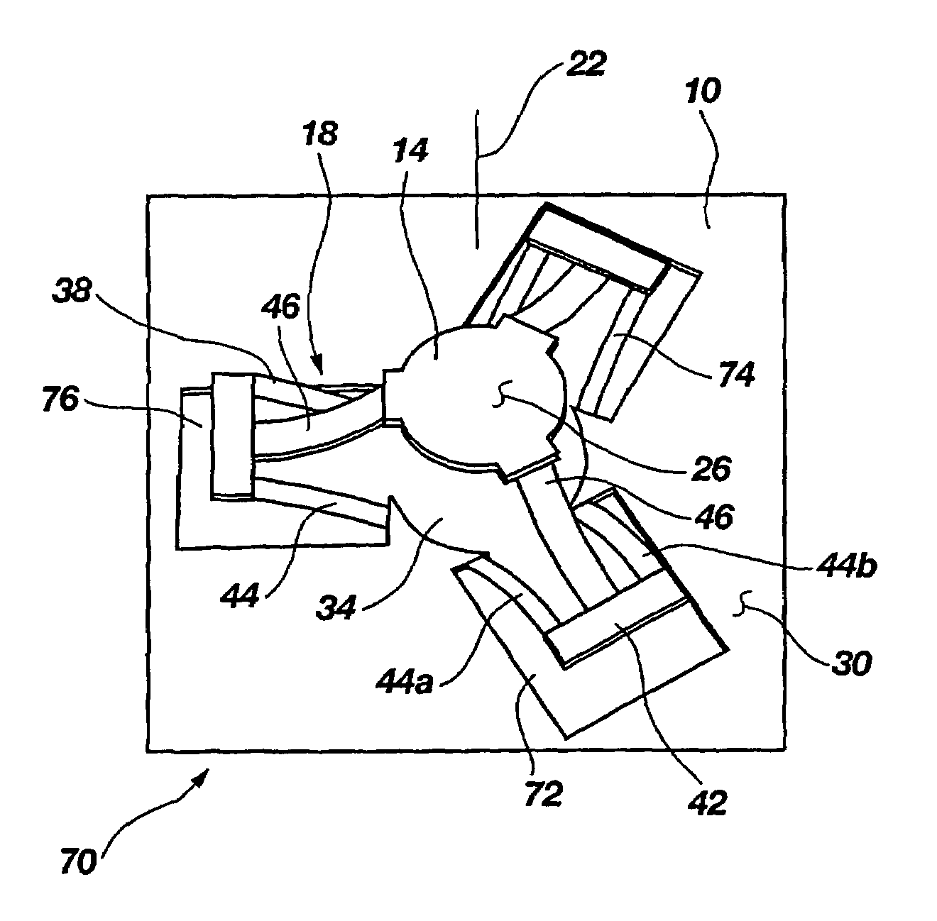
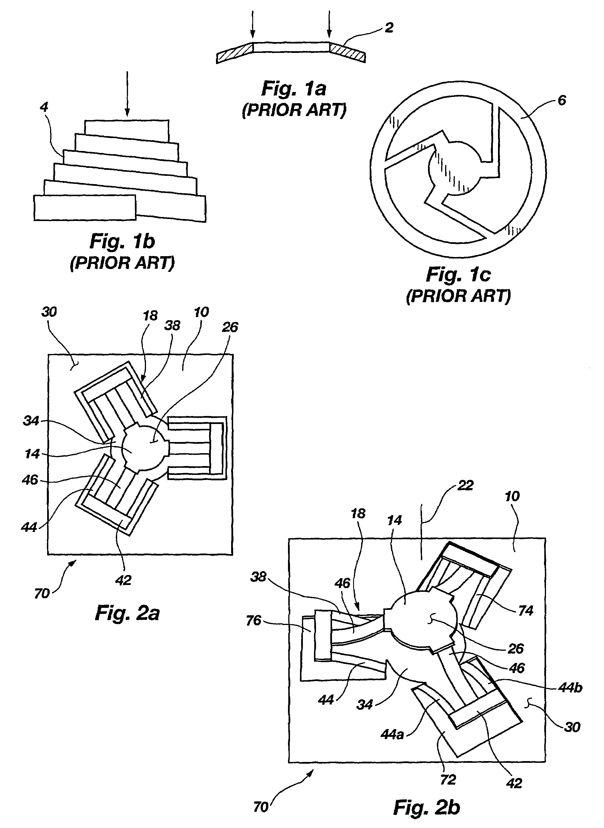
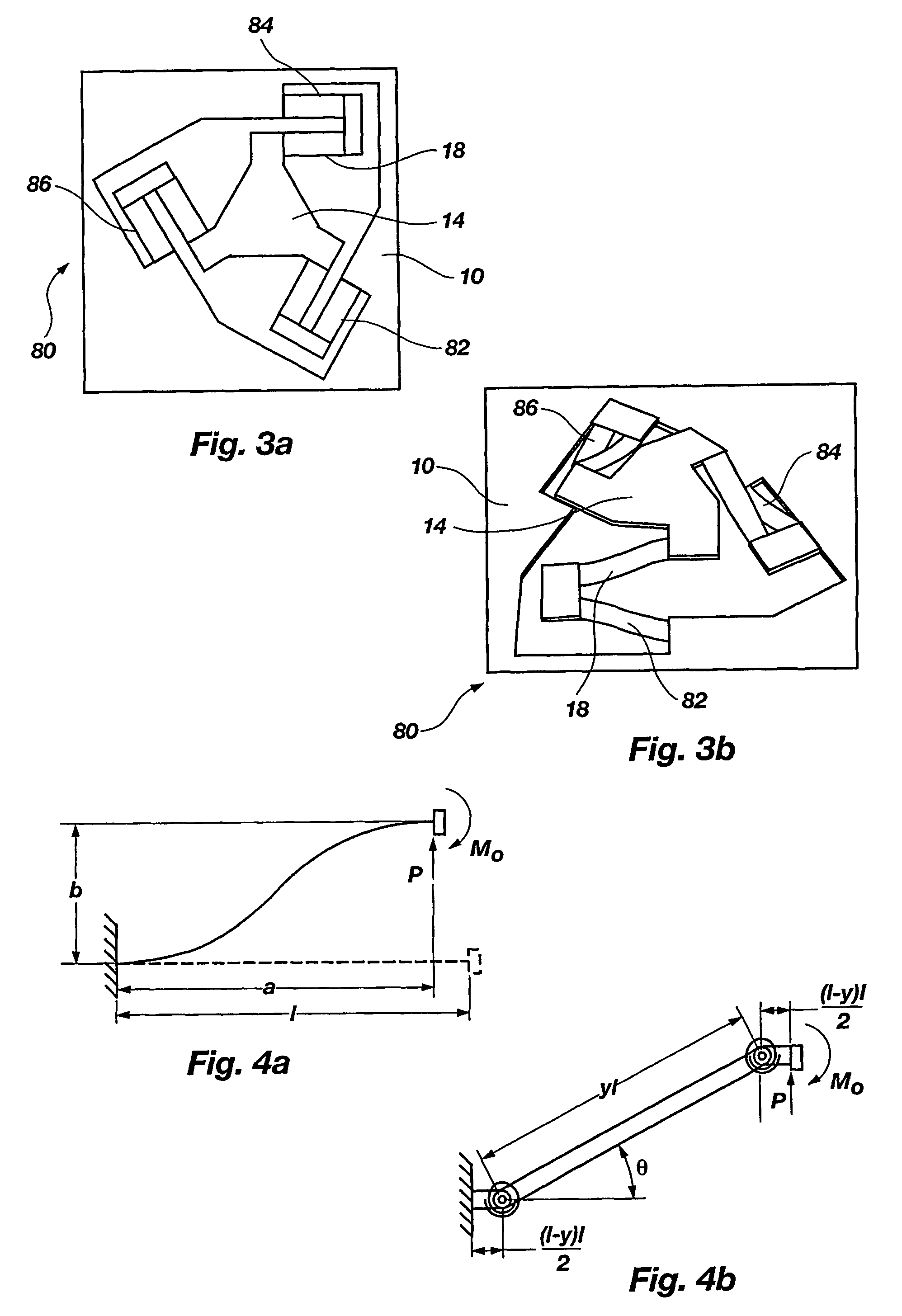
[0057]As illustrated in the Figures, a new type of ortho-planar spring has been designed that has the potential of possessing all of the advantages of conventional ortho-planar springs, without most of the disadvantages. This new spring operates by raising or lowering its platform relative to the base without ...


PUM


Abstract

An ortho-planar spring has a platform movably coupled to a base and being movable linearly with respect to the base along at least a portion of an axial direction perpendicular to both a base surface and a platform surface. A resilient and flexible connecting structure is connected to and between the base and platform. The connecting structure is bendable to develop (i) an axial force along the axial direction to bias the platform in a stable position with respect to the base, and (ii) non-axial forces which substantially sum to zero to preserve the orientation of the platform with respect to the base. Thus, the spring is very compact and does not have rotation between the deflecting ends. The spring may be associated with a valve opening, and a button for restricting flow through the valve opening, to bias the button at a position with respect to the valve opening.

Description

[0001]This application claims the benefit of provisional application No. 60 / 199,905 filed Apr. 26, 2000.[0002]The U.S. Government has rights to this invention pursuant to Grant No. MSS-8902777 awarded by the National Science Foundation.BACKGROUND OF THE INVENTION[0003]1. The Field of the Invention[0004]The present invention relates generally to a spring, which are particularly useful in pneumatic instruments, such as valve controllers. More particularly, the present invention relates to springs that can be fabricated, or compressed, into a single plane, but have motion out of that plan, and one-piece, compliant springs with a platform that does not have substantial rotation throughout its deflection.[0005]2. The Background Art[0006]An ortho-planar spring can be defined as a spring which can be either fabricated in or compressed down into a single plane, with motion out of that plane. Prior art that fit this definition are the Belleville or disc spring 2 (FIG. 1a), the volute (conica...

Claims


Application Information

Patent Timeline
IPC IPC(8): F16F1/34F16F1/02F16F1/32F16F3/02F16F15/073
CPCF16F1/027F16F1/324F16F3/023F16F15/073F16F3/026Y10S251/902F16F2236/027
Inventor HOWELL, LARRY L.THOMSON, SCOTTBRISCOE, JASON ALANPARISE, JOHN J.LORENC, SHAELARSEN, JOHN B.HUFFMIRE, CURTIS R.BURNSIDE, NATHANGOMM, TROY A.
Owner BRIGHAM YOUNG UNIV
Learn More