
Ink jet head

a jet head and jet technology, applied in printing and other directions, can solve the problems of difficult comparison of discharge direction and misdirection of discharge direction, and achieve the effect of reducing the necessary current value, reducing the size of main liquid droplets, and suppressing the increase of current quantities

Inactive Publication Date: 2006-01-10
CANON KK
View PDF19 Cites 33 Cited by
  • Summary
  • Abstract
  • Description
  • Claims
  • Application Information

AI Technical Summary

Benefits of technology

[0012]Accordingly, the present invention aims to provide an ink jet head capable of discharging ink liquid droplets from a discharge port efficiently without any discharge direction shifts even if the center position of the discharge port and the center position of a pressure generating area are somewhat shifted from each other.
[0014]According to the ink jet head of the present invention, even if the center position of the discharge port and the center position of the pressure generating area are somewhat shifted from each other, the influence of the distribution of foaming in the plurality of heat generating members, and the possibility of touches of the liquid columns of the ink discharged through the discharge port to the side walls of the discharge port is remarkably decreased. Consequently, the main liquid droplets of the ink are discharged from the discharge port without any shifts of the discharge directions. Moreover, if the liquid columns do not touch the side wall surfaces of the discharge walls of the discharge port, the parts where the main droplets are separated from the liquid columns are fixed. Consequently, it becomes possible to stable the sizes of the main liquid droplets, namely the sized of the dots formed by the main droplets placed on a sheet of recording paper, or the like.
[0015]Moreover, by adopting the configuration in which these plural heat generating members are connected to each other in series electrically with wiring, a resistance value higher than that of a single heat generating member having the same size as that of the plural heat generating members can be obtained, which makes it possible to reduce the necessary current value. Consequently, if the speed of discharge operation is intended to be high as discharged liquid droplets become smaller, it is possible to suppress the increase of current quantities flowing through the heat generating members. Moreover, it is possible to suppress heat generation and voltage drops owing to the resistance of a wiring section up to the heat generating members, and further to suppress induction noises generated by large currents flowing through the wiring section.
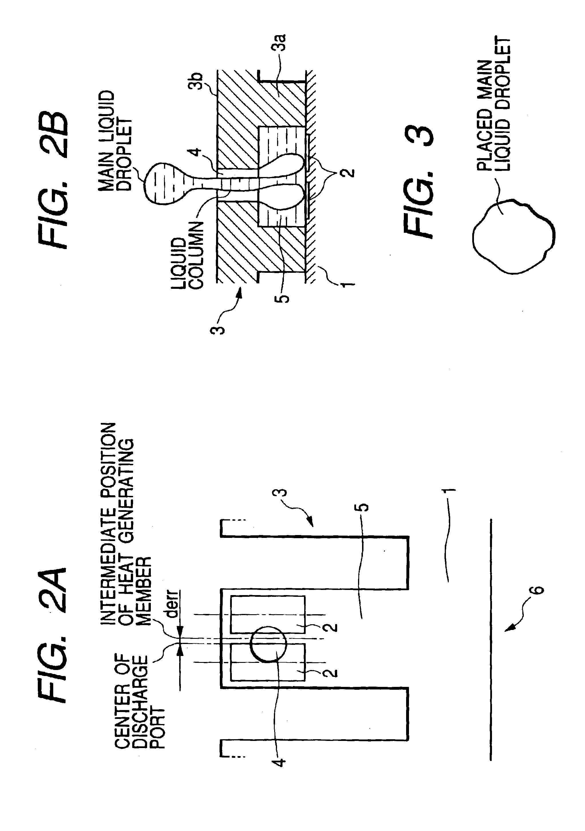
[0016]Moreover, by adopting the configuration in which, when a shift quantity of the center of the discharge port to the extension line is designated by derr, the distance dhc, the diameter do of the aperture, and the shift quantity derr satisfy a relation: dhc>do+derr×2, it becomes possible to place minute liquid droplets generated at separation portions between main liquid droplets and liquid columns at impact positions of the main droplets. Furthermore, it also becomes possible to stable the impact positions of the main liquid droplets. Consequently, the shapes and positions of dots formed by the placed liquid droplets can be stabled.
[0017]Moreover, by adopting the configuration in which at least two heat generating members among the plurality of heat generating members provided in each of the ink flow passages are arranged with a certain interval dhh with respect to a direction between partition walls partitioning each of the ink flow passages; and the interval dhh between two heat generating members adjoining to each other most apart from each other with respect to the direction between the partition walls among the plurality of heat generating members is twice or less as long as an interval dhn between each of the partition walls and the heat generating members adjoining the each of the partition walls, it is prevented that bubble remaining in ink stay in an area between the two heat generating members. Consequently, the stability of discharging ink is further heightened.
[0019]According to the ink jet head of the present invention, even if the center position of the discharge port and the center position of the pressure generating area are somewhat shifted from each other, the deviations of the flight directions of the liquid droplets, which deviations can be produced by a heat generating member on one side of the two heat generating members, and the deviations of the flight directions of the liquid droplets, which deviations can be produced by the other heat generating member on the other side of the two heat generating members, are produced in the directions opposite to each other. Consequently, the deviations of the flight directions of the liquid droplets, which deviations can be produced by a heat generating member on one side, are cancelled by the deviations of the flight directions of the liquid droplets, which deviations can be produced by the other heat generating member on the other side. Therefore, the deviations of the flight directions of the liquid droplets can be reduced, and the discharge directions of the liquid droplets can be stabled.

Problems solved by technology

In particular, since the misdirection of a discharge direction seriously affects an image in case of a smaller ink liquid droplet in comparison with a conventional ink liquid droplet, it is further required to make it difficult to generate the misdirection of the discharge direction in comparison with in the case of the prior art.

Method used


Image

  • Ink jet head
  • Ink jet head
  • Ink jet head

Examples


first embodiment

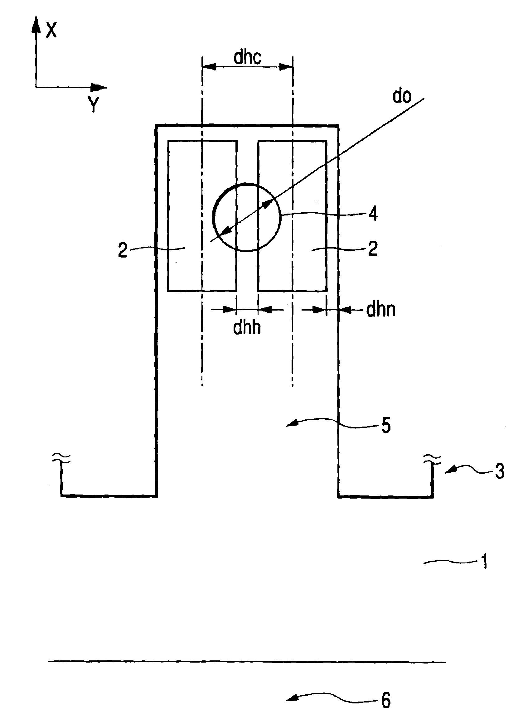
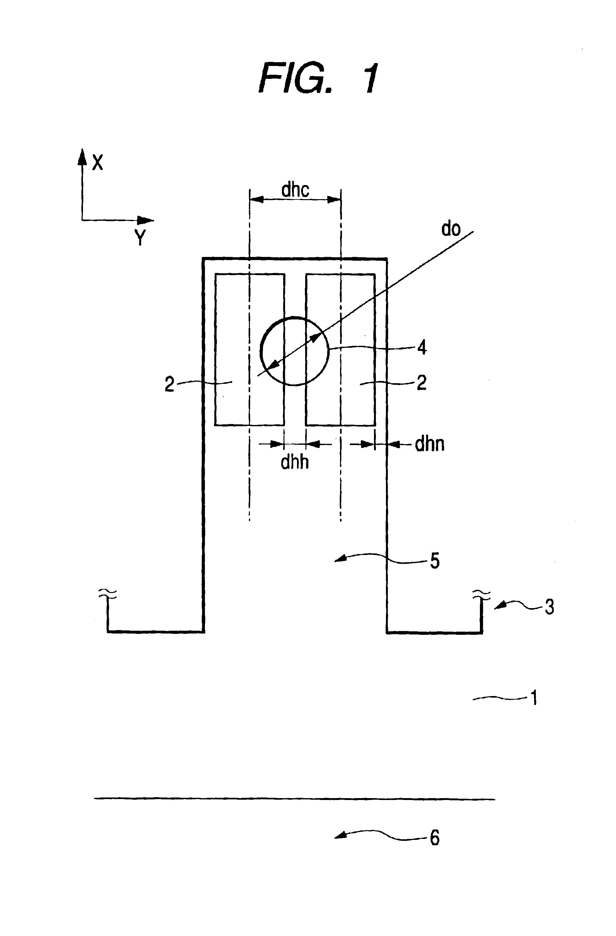
[0034]FIG. 1 is a transparent plan view showing an arrangement relationship of an ink flow path, heat generating members and a discharge port in an ink jet head of a first embodiment of the present invention.

[0035]The ink jet head of the present embodiment includes a substrate 1 provided with many heat generating members 2 on the surface thereof, and a flow passage forming member 3 provided on the substrate 1. The flow passage forming member 3 includes partition walls 3a for partitioning the many heat generating members 2 into twos, and a ceiling wall 3b opposed to the substrate 1. The partition walls 3a form a plurality of ink flow passages 5 for feeding ink into pressure generating areas composed of the two heat generating members 2 partitioned by the partitioned walls 3a. Moreover, in each ink flow passage 5, a discharge port 4 is formed in the ceiling wall 3b on an extension line extending from the center of a pressure generation area, composed of two heat generating members 2, ...

second embodiment

[0050]FIGS. 4A and 4B are views showing an arrangement relationship of an ink flow passage, heat generating members and a discharge port of an ink jet head of a second embodiment of the present invention. FIG. 4A is a plan view thereof, and FIG. 4B is a sectional view thereof.

[0051]As shown in FIG. 4A, especially, the ink jet head of the present embodiment is provided with a pressure generating area composed of four-in-a-set heat generating members 2 in one ink flow passage 5. Supposing that the ink flow direction in the ink flow passage 5 is an X direction and a direction orthogonal to the X direction is a Y direction, these heat generating members 2 are arranged in the way in which two of them are arrange in the X direction and two of them are arranged in the Y direction. Moreover, these heat generating members 2 are connected in series electrically by wiring. A discharge port 4 is arranged on an extension line extending from the center of the pressure generating area composed of ...

third embodiment

[0057]FIG. 5 is a transparent plan view showing an arrangement relationship of an ink flow passage, heat generating members and a discharge port of an ink jet head of a third embodiment of the present invention.

[0058]As in the case with the first embodiment, the third embodiment is provided with two heat generating members 2 which have a slender shape and are arranged in one ink flow passage 5. The other configurations of the recording head are also the same as those of the first embodiment.

[0059]In the present embodiment, the width of each heat generating member 2 was set to be 11 μm; the length thereof was set to be 27 μm; the interval dhh of the two heat generating members 2 was set to be 4 μm; and the distance dhc between the centers of the two heat generating members 2 was set to be 15 μm. Moreover, the diameter do of the aperture of the discharge port 4 was set to be 10.5 μm, and the height OH of the aperture plane of the discharge port 4 from the top surface of a substrate 1 ...


PUM


Abstract

An ink jet head includes a substrate provided with heat generating members for generating a bubble in ink on a surface of the substrate, a plurality of discharge ports for discharging the ink, the ports opposed to the surface of the substrate, and a plurality of ink flow passages communicating with the plurality of discharge ports to feed the ink. A plurality of the heat generating members is provided in each of the ink flow passages, and the discharge port is arranged on an extension line extending from a center of a pressure generating area composed of the plurality of heat generating members toward the surface of the substrate in a normal direction. Moreover, a distance dhc between centers of each of two heat generating members arranged most apart from each other among the plurality of heat generating members is set to be larger than a diameter do of an aperture of the discharge port. In the ink jet head, even if the center position of the discharge port and the center position of the pressure generating area are somewhat shifted from each other, main liquid droplets of the ink are discharged from the discharge port without generating no shift in their discharge directions.

Description

BACKGROUND OF THE INVENTION[0001]1. Field of the Invention[0002]The present invention relates to an ink jet head for performing record by discharging ink to a recording medium.[0003]2. Description of Related Art[0004]In recent years, an ink jet recording apparatus has been widely used especially as an output device of a computer because a high definition character and an image can easily be obtained by means of the ink jet recording apparatus. Inter alia, the bubble jet system for discharging ink from nozzles by means of a sudden pressure change produced by boiling the ink in the nozzle rapidly has become the main stream of the ink jet recording apparatus since many nozzles can easily be arranged in a high density in a simple configuration by the bubble jet system.[0005]Moreover, as the ink jet recording apparatus has been widely spread in recent years, demands for the performances of the ink jet recording apparatus, especially for the image quality thereof and the recording speed t...

Claims


Application Information

Patent Timeline
IPC IPC(8): B41J2/05B41J2/14
CPCB41J2/14056B41J2002/14387B41J2002/14185B41J2002/14169B41J2/14
Inventor KANEKO, MINEOTSUCHII, KENTSUKUDA, KEIICHIROOIKAWA, MASAKIYABE, KENJI
Owner CANON KK
Learn More