Multilayered microfluidic DNA analysis system and method

a microfluidic and microfluidic technology, applied in the field of dna amplification and analysis, can solve the problems of silicon, affecting the efficiency of microfluidic devices, and the cost of silicon microfluidic devices can be relatively high, and achieve the effect of saving time and expens

Inactive Publication Date: 2006-01-10
GOOGLE TECH HLDG LLC
View PDF3 Cites 141 Cited by
  • Summary
  • Abstract
  • Description
  • Claims
  • Application Information

AI Technical Summary

Problems solved by technology

Next, the DNA is typically separated from the rest of the cell contents, as the presence of other cell contents may be undesirable in subsequent steps.
The ability to perform all of these steps in a single miniaturized device has the potential for saving time and expense.
Silicon, however, suffers from a number of disadvantages as a substrate material.
The cost of fabricating microfluidic devices in silicon can be relatively high.
Silicon's high thermal conductivity can make the thermal cycling needed to perform PCR difficult, and silicon's property of being electrically semiconducting can hamper the operation of components that require the maintenance of a high potential difference.
Most importantly, however, the difficulty of bonding multiple layers of silicon together makes it difficult to integrate complex components into the device.

Method used


Image

  • Multilayered microfluidic DNA analysis system and method
  • Multilayered microfluidic DNA analysis system and method
  • Multilayered microfluidic DNA analysis system and method

Examples


Embodiment Construction

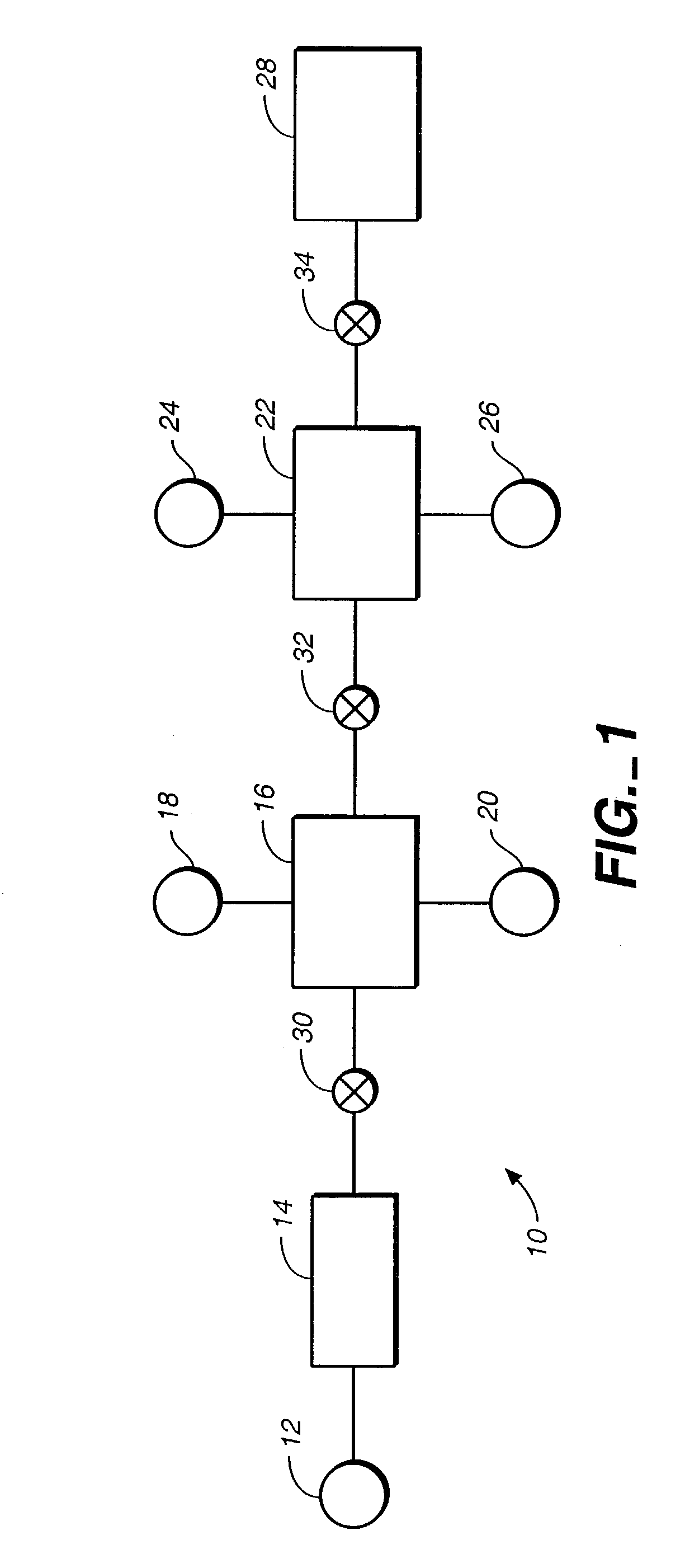
[0018]Shown schematically in FIG. 1 is a microfluidic DNA analysis system 10, in accordance with a preferred embodiment of the present invention. A sample inlet port 12 is in fluid communication with a cell lysis chamber 14, and cell lysis chamber 14 is in fluid communication with a DNA separation chamber 16. A buffer injection port 18 and a waste outlet port 20 are preferably provided in fluid communication with DNA separation chamber 16. A DNA amplification chamber 22 is in fluid communication with DNA separation chamber 16. A reagent injection port 24 and a waste outlet port 26 are preferably provided in fluid communication with DNA amplification chamber 22. Finally, a DNA detection system 28 is in fluid communication with DNA amplification chamber 22.

[0019]Preferably, a first fluid flow control system 30 is provided between cell lysis chamber 14 and DNA separation chamber 16 and a second fluid flow control system 32 is provided between DNA separation chamber 16 and DNA amplifica...


PUM

PropertyMeasurementUnit
electric field strengthaaaaaaaaaa
diametersaaaaaaaaaa
temperatureaaaaaaaaaa

Abstract

A multilayered microfluidic DNA analysis system includes a cell lysis chamber, a DNA separation chamber, a DNA amplification chamber, and a DNA detection system. The multilayered microfluidic DNA analysis system is provided as a substantially monolithic structure formed from a plurality of green-sheet layers sintered together. The substantially monolithic structure has defined therein a means for heating the DNA amplification chamber and a means for cooling the DNA amplification chamber. The means for heating and means for cooling operate to cycle the temperature of the DNA amplification chamber as required for performing a DNA amplification process, such as PCR.

Description

CROSS-REFERENCE TO RELATED APPLICATIONS[0001]This application is a divisional of application U.S. Ser. No. 09 / 460,281, filed on Dec. 9, 1999, now U.S. Pat. No. 6,544,734, hereby incorporated by reference, which is a continuation-in-part of U.S. application Ser. No. 09 / 337,086, filed on Jun. 21, 1999, now U.S. Pat. No. 6,572,830, which is a continuation-in-part of U.S. application Ser. No. 09 / 235,081, filed on Jan. 21, 1999, now U.S. Pat. No. 6,592,696, which, in turn, claims the benefit of U.S. Provisional Application No. 60 / 103,701, filed Oct. 9, 1998. The disclosure of U.S. application Ser. No. 09 / 337,086 is fully incorporated herein by reference.BACKGROUND OF THE INVENTION[0002]1. Field of the Invention[0003]This invention relates to the field of DNA amplification and analysis. More particularly, this invention relates to a system and method for releasing DNA from cells, for amplifying the DNA, and for detecting the amplified DNA products, wherein the device is formed from multip...

Claims


Application Information

Patent Timeline
Patent Type & Authority Patents(United States)
IPC IPC(8): C12M1/34C12P19/34B01J19/08B01J19/00G01N35/08B01J19/24B01J35/02B01L3/00B01L7/00B28B11/00B32B18/00B81B1/00C12M1/00C40B60/14F04B19/00F28D9/00F28F13/00G01N30/02G01N30/52G01N30/60G01N35/00G01N37/00H05K1/02H05K1/03H05K3/46
CPCF04B19/006F28D9/00F28F13/00G01N30/60G01N30/6069G01N30/6095B01J19/0093B01L3/502707B01L3/50273B01L7/00B01L7/52B32B18/00B81C1/00119B81C2201/019C04B2237/704C04B2237/348C04B2237/50C40B60/14F28D2021/0029F28F2260/02G01N30/6004G01N2030/025G01N2030/528G01N2035/00158G01N2035/00237H05K1/0272H05K1/0306H05K3/4611H05K3/4629B01J2219/00317B01J2219/00351B01J2219/00495B01J2219/00783B01J2219/00835B01J2219/00873B01J2219/00966B01L3/502738B01L2200/0689B01L2200/12B01L2300/0627B01L2300/0645B01L2300/0874B01L2300/0883B01L2300/0887B01L2300/12B01L2300/18B01L2300/1822B01L2400/0415B01L2400/0439B32B2038/042B32B2311/06B32B2311/08B32B2315/02B81B2201/058C04B2235/6562C04B2237/341C04B2237/62C04B2237/68C04B2237/343
Inventor BRISCOE, CYNTHIA G.YU, HUINANGRODZINSKI, PIOTRMARRERO, ROBERTBURDON, JEREMY W.HUANG, RONG-FONG
Owner GOOGLE TECH HLDG LLC
Why Eureka
Try Eureka