Electron microscope and method for controlling focus position thereof

a technology of electron microscope and focus position, which is applied in the field of electron microscope, can solve the problems of increasing the problem, difficulty in automatic adjustment method, and difficulty in carrying out automation

Inactive Publication Date: 2006-01-10
RIKEN
View PDF9 Cites 11 Cited by
  • Summary
  • Abstract
  • Description
  • Claims
  • Application Information

AI Technical Summary

Benefits of technology

[0009]It is therefore an object of the present invention to eliminate the above described problems in the prior art and to provide an electron microscope capable of simp

Problems solved by technology

In a case where the electron optical system of an electron microscope is intended to be automatically adjusted, it is not easy to carry out automation similar to the automatic focusing function of general purpose optical cameras, video cameras or the like.
However, the irradiation damage of a sample causes a problem, so that the adjusting method for acquiring many images further increases this problem.
This makes the automatic adjusting method difficult.
The specific aberration characteristics of electron microscopes also make the adjusting method difficult.
Since there are two adjusting quantities (with respect to x and y directions) in the adjustment of astigmatism correction, the adjusting method is further complicated, so that it is difficult to carry out the adjusting method.
In addition, unlike optical lens systems, spherical aberration can not be corrected except for very special cases.
Particularly in high resolution electron microscopes, optimum conditions c

Method used


Image

  • Electron microscope and method for controlling focus position thereof
  • Electron microscope and method for controlling focus position thereof
  • Electron microscope and method for controlling focus position thereof

Examples


Embodiment Construction

[0032]Referring to the accompanying drawings, the preferred embodiment of an electron microscope and a method for controlling its focus position according to the present invention will be described below.

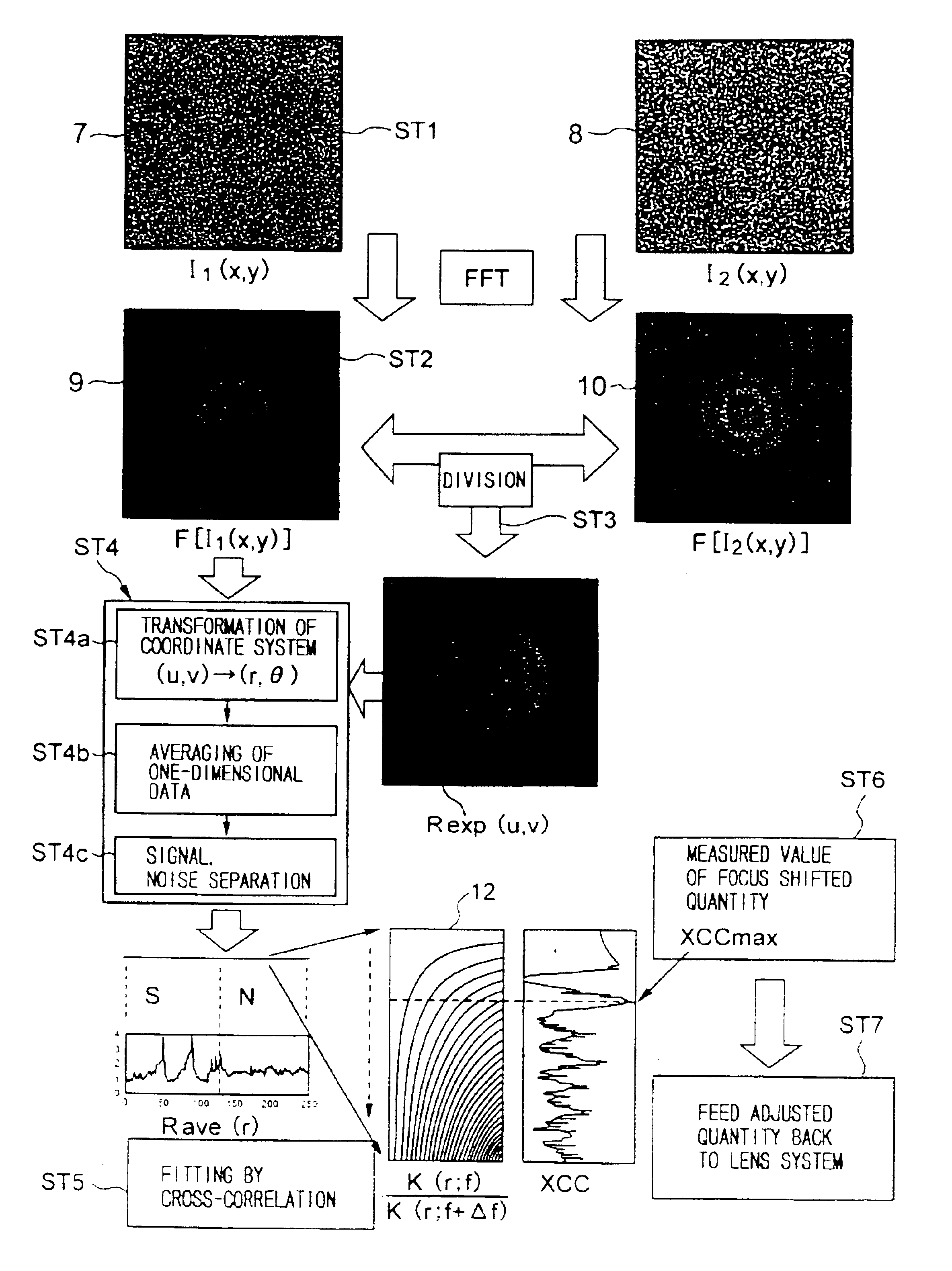
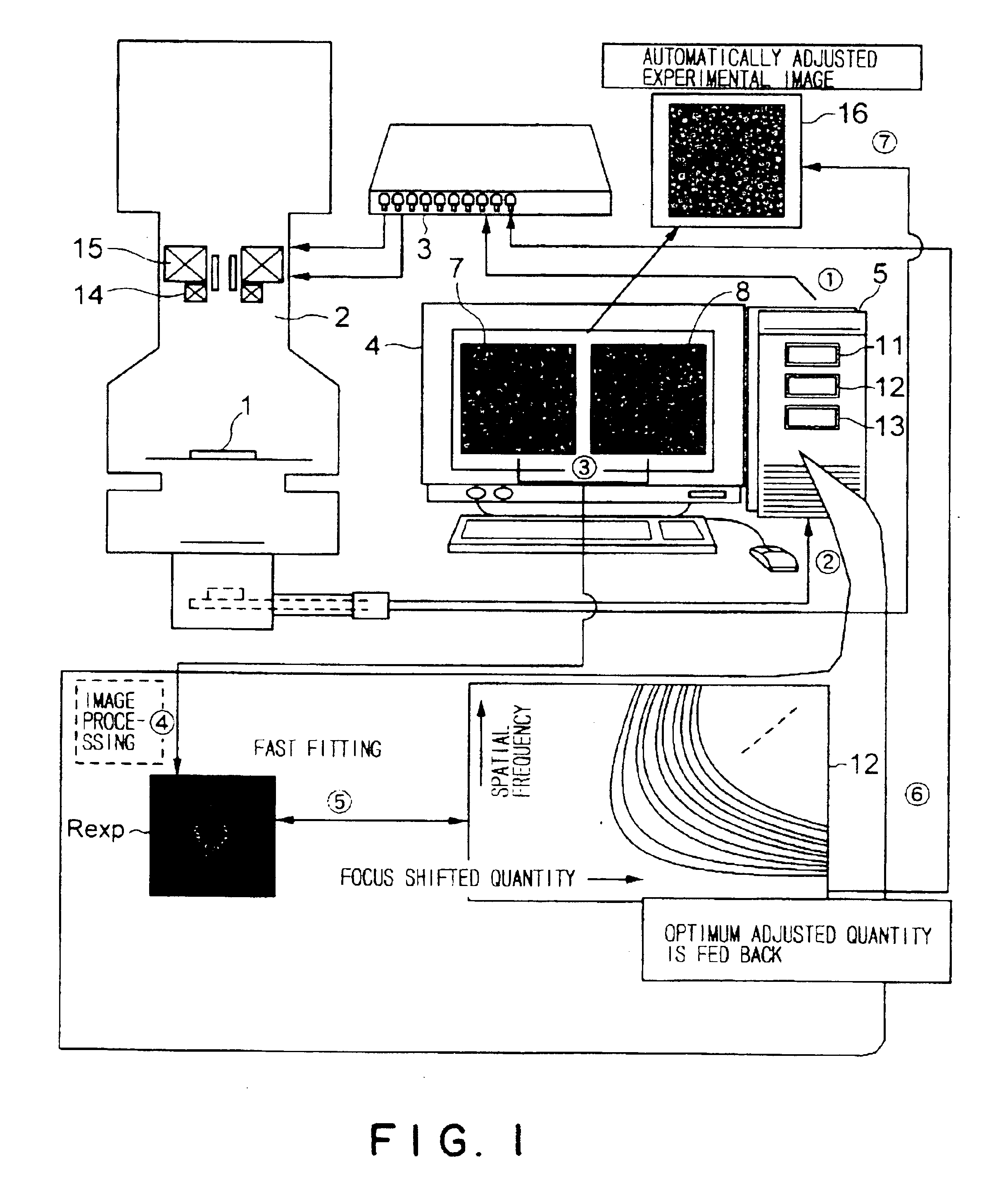
[0033]The present invention is intended to detect first and second two images at two focus positions, which are realized by changing a predetermined physical quantity only by a known quantity, to compare the detected results with theoretical data to recognize the electron optical state of an electron microscope to automatically adjust its focus position and / or astigmatism. The predetermined physical quantity may be any physical quantity univocally influencing the focus position of the electron microscope. The predetermined physical quantity should not be limited to the focus position, but it may be another physical quantity, e.g., an accelerating voltage of electron beams. In the following descriptions, the focus position itself will be used as an example of a predetermined physical...


PUM


Abstract

There are provided an electron microscope capable of carrying out focusing and astigmatism correction without depending on characteristics of a sample, and a method for controlling its focus position.
The electron microscope according to the present invention comprises: an electron optical system (2); a focus control part (3); an image detecting part (4); a first operating part (11) for mutually dividing first and second transformed images (9) and (10), which are obtained by carrying out the fast Fourier transform of first and second images (7) and (8) detected at two focus positions of a first focus position (f1) and a second focus position (f2) shifted from the first focus position by a known focus shifted quantity Δf, to obtain a measured divided quantity Rexp; divided quantity data (12) previously prepared and stored as a function of focus positions and spatial frequencies as a set of theoretical divided quantities, the theoretical divided quantities being obtained by substituting the two focus positions shifted by the focus shifted quantity Δf for an image transfer function (r,f) to obtain first and second transfer function values K(r;f) and (r;f+Δf) to mutually divide the first and second transfer function values K(r;f1) and (r;f+Δf) on a spatial frequency plane; and a second operating part (13) for making a reference to the divided quantity data (12) to derive a theoretical divided quantity K(r;f0) correlating to the measured divided quantity Rexp, and for deriving a focus position f0 corresponding to the derived theoretical divided quantity K(r;f0)/K(r;f0+Δf) as a first focus position f1.

Description

TECHNICAL FIELD[0001]The present invention relates generally to an electron microscope and a method for controlling the focus position thereof. More specifically, the invention relates to an electron microscope capable of automatically correcting its focus position and astigmatism, and a method for controlling the focus position.BACKGROUND ART[0002]In a case where the electron optical system of an electron microscope is intended to be automatically adjusted, it is not easy to carry out automation similar to the automatic focusing function of general purpose optical cameras, video cameras or the like. The main reasons for this include (1) problems on S / N ratio and (2) aberration characteristics.[0003]The S / N ratio of electron microscope images is low unlike general images, so that the processing of the differential system of picture signals does not function. If an image having a high S / N ratio is intended to be obtained, the dose of electron beams must be increased. However, the irr...

Claims


Application Information

Patent Timeline
IPC IPC(8): H01J37/21H01J37/153G02B7/28H01J37/22
CPCH01J37/22H01J2237/216
Inventor IWAKI, MASAYABABA, NORIO
Owner RIKEN
Why Eureka
Try Eureka