
Dual domain differential encoder/decoder

a differential encoder and differential encoder technology, applied in the field of data communication, can solve problems such as loss of information, system performance loss, and noise increas

Active Publication Date: 2006-01-10
BENHOV GMBH LLC
View PDF11 Cites 19 Cited by
  • Summary
  • Abstract
  • Description
  • Claims
  • Application Information

AI Technical Summary

Benefits of technology

"The present invention provides methods and apparatuses for differentially encoding and decoding symbols on a plurality of sub-carriers. The invention allows for the efficient and accurate transmission of information using a minimum number of sub-carriers. The invention also provides a method for sequentially encoding and decoding symbols across frequency and time to improve the accuracy and reliability of the transmission process. The technical effects of the invention include improved data transmission speed, reduced latency, and improved reliability."

Problems solved by technology

As the symbol decoding in the differential decoding process are taken from positions further apart in either time or frequency, the affects of noise increase.
The originally transmitted information is correlated in time and frequency as it is generated, and the effects of noise tend to decorrelate the information.
In the case of pulse or intermittent transmission systems, the fact that differential encoding and decoding requires two carrier states for the transmission of each symbol can result in a loss of information, and therefore a loss in system performance, which is typically measured as a reduced signal to noise ratio.
Either by limited allocation of radio spectrum in the case of radio transmission systems, or in limited transmission capabilities of wireline systems, which include inductive, resistive, and capacitive losses.

Method used


Image

  • Dual domain differential encoder/decoder
  • Dual domain differential encoder/decoder
  • Dual domain differential encoder/decoder

Examples


Embodiment Construction

[0029]Illustrative embodiments and exemplary applications will now be described with reference to the accompanying drawings to disclose the advantageous teachings of the present invention.

[0030]While the present invention is described herein with reference to illustrative embodiments for particular applications, it should be understood that the invention is not limited thereto. Those having ordinary skill in the art and access to the teachings provided herein will recognize additional modifications, applications, and embodiments within the scope thereof and additional fields in which the present invention would be of significant utility.

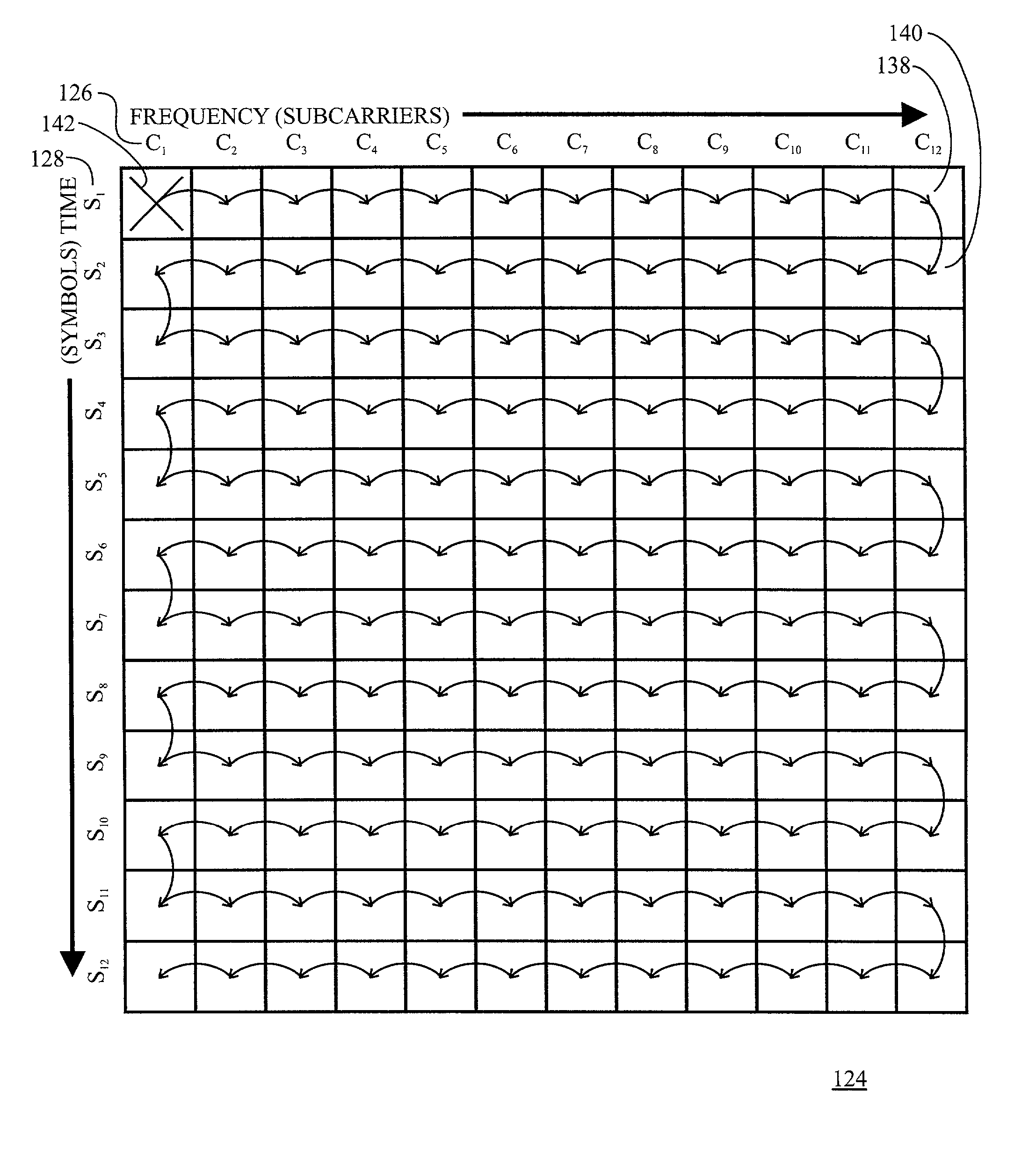
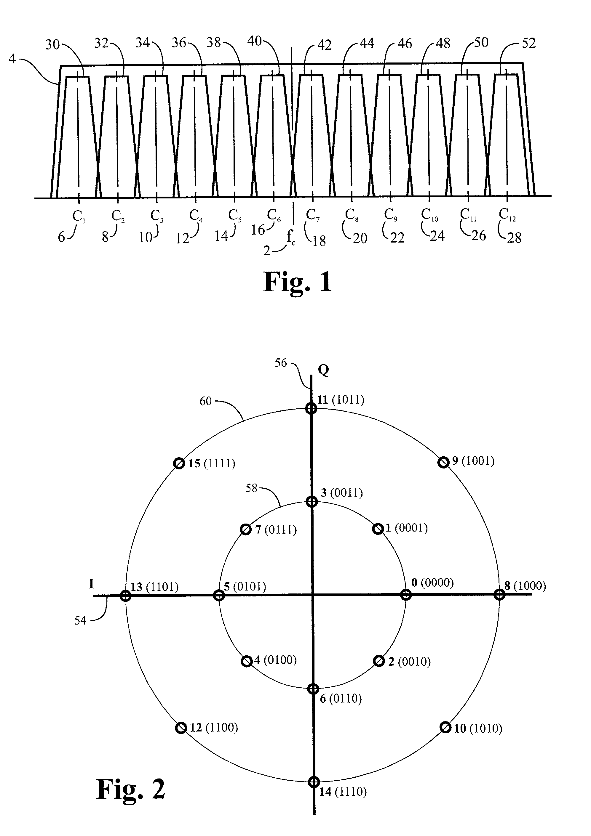
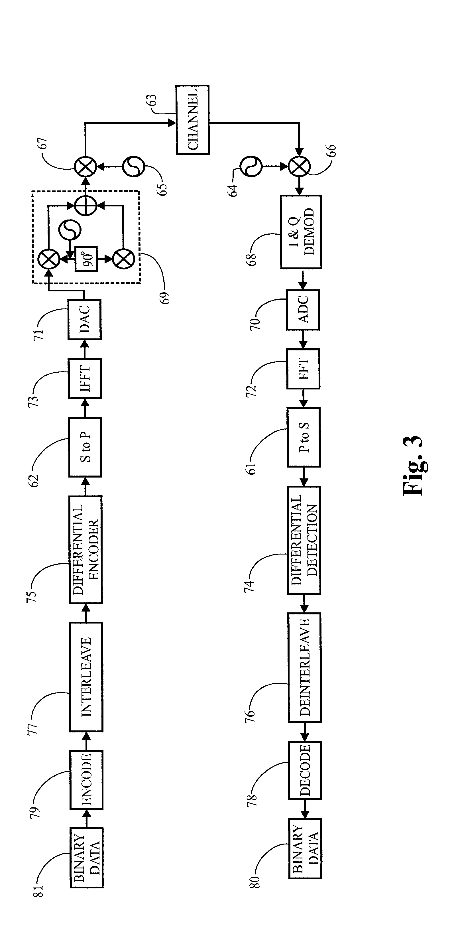
[0031]Reference is directed to FIG. 1, which is a spectrum channelization diagram of an illustrative embodiment of the present invention. This illustration is directed toward a radio communications implementation of the present invention, although, the present invention is equally applicable to a system employing wireline or fiber communications. In ...


PUM


Abstract

A method and apparatus that differentially encodes and decodes data symbols in dual domains is taught. Data packets are encoded, transmitted, and decoded during a plurality of symbol intervals on a plurality of sub-carriers. Encoding and decoding are accomplished across both the time and frequency domains such that the minimum number of carrier states are employed as reference only states that do not encode a symbol of data in and of themselves. A rule of adjacency is followed, both across time and frequency, so that decorrelation is minimized. Any modulation scheme that is applicable to differential encoding and decoding can be utilized. Communication systems that couple via radio waves, through metallic conductors, or over fiber optic paths can be employed.

Description

BACKGROUND OF THE INVENTION[0001]1. Field of the Invention[0002]The present invention relates to data communications. More specifically, the present invention relates to differentially encoded and decoded communications systems that communicate information across a plurality of sub-carriers within intermittently transmitted blocks of information.[0003]2. Description of the Related Art[0004]Modern communications systems have advantageously employed the use of multiple sub-carriers as a means of utilizing available bandwidth. Two examples of such use include orthogonal frequency division multiplexed systems (“OFDM”) and multiple-carrier transmission systems (“MCT”). In multiple-carrier transmission and OFDM systems, a given portion of bandwidth is sub-divided into several sub-bands and information is modulated onto each of the sub-bands. MCT systems are particularly suitable for the implementation of a frequency division multiplexed multiple access (“FDMA”) systems.[0005]FDMA system p...

Claims


Application Information

Patent Timeline
Patent Type & Authority Patents(United States)
IPC IPC(8): H04B14/06H04L27/26
CPCH04L27/2602
Inventor MCCARTY, JR., ROBERT J.
Owner BENHOV GMBH LLC
Learn More