
Image processing system, image processing apparatus, and image processing method

Inactive Publication Date: 2006-01-10
CANON KK
View PDF9 Cites 47 Cited by
  • Summary
  • Abstract
  • Description
  • Claims
  • Application Information

AI Technical Summary

Benefits of technology

[0007]The present invention has been made in consideration of the conventional problems, and has as its object to provide an image processing system, image processing apparatus, and image processing method, which can remove noise contained in an original image upon compressing / decompressing an image.
[0014]a decoding device for restoring the transform coefficients from the code sequence, reclaiming a reference image on the basis of the transform coefficients of a given frequency range of the restored transform coefficients, and removing noise by processing the transform coefficients of the frequency ranges other than the given frequency range on the basis of the reference image.
[0015]An image processing apparatus according to the present invention is an image processing apparatus for encoding an image, which generates a code sequence by encoding an image in units of bit planes, and removes noise on the image by deleting data of bit planes of levels lower than a lower-limit bit plane.
[0016]Another image processing apparatus according to the present invention is an image processing apparatus for decoding an image, which reclaims an image by decoding an image in units of bit planes, and removes noise on the image by deleting data of bit planes of levels lower than a lower-limit bit plane.
[0018]removes noise by processing the transform coefficients of frequency ranges other than the given frequency range on the basis of the reference image.

Problems solved by technology

However, no technique for effectively reducing noise in the image encoding / decoding process has been proposed yet.
But an image sensed with a small X-ray dosage contains many quantization noise components, which disturb diagnosis.
Also, when this method is combined with image coding, flexible adjustment of image quality is disturbed upon display.

Method used


Image

  • Image processing system, image processing apparatus, and image processing method
  • Image processing system, image processing apparatus, and image processing method
  • Image processing system, image processing apparatus, and image processing method

Examples


first embodiment

[First Embodiment]

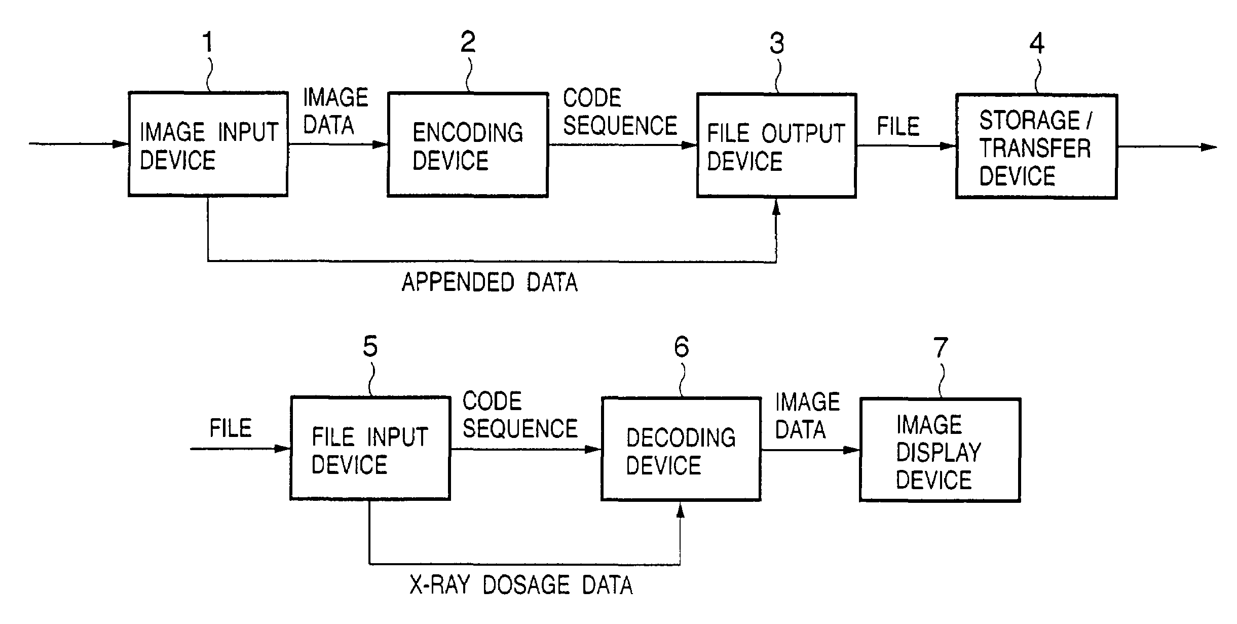
[0079]An image processing system for executing a series of processes when medical images are processed as an electronic format according to the first embodiment of the present invention will be described.

[0080]FIG. 1 shows a schematic arrangement of an image processing system of this embodiment. Referring to FIG. 1, an image input device 1 is an image sensing device using X-rays, and generates and outputs required images using a sensor corresponding to a purpose intended. An image generated by this device has a resolution of 2500×2500 pixels (vertical×horizontal) or higher, and the precision of each pixel is expressed by 12 bits. Since a large-size storage medium is required to save such image having high resolution and high pixel precision as a raw image, the image undergoes compression coding as needed.

[0081]An encoding device 2 in FIG. 1 is used to compress such image, and reversibly or irreversibly compression-encodes an image input from the image input device ...

second embodiment

[Second Embodiment]

[0114]In the decoding device of the first embodiment, the lower-limit bit plane of the transform coefficient to be decoded is controlled in accordance with the noise amount ε. But in some cases, a noise removal process need be controlled more flexibly. As the second embodiment of the present invention devised to this end, a decoding device having an arrangement for implementing a noise removal process by finer control will be explained. Since the arrangement of the overall image processing system and building components other than the decoding device 6 are the same as those in the first embodiment, a description thereof will be omitted.

[0115]FIG. 12 shows an arrangement of the decoding device 6 according to this embodiment.

[0116]Referring to FIG. 12, a code sequence output from the code input unit 601 is decoded by the entropy decoder 602 in units of bit planes. In this embodiment, the entropy decoder 602 decodes all the input bit planes, and outputs restored tran...

third embodiment

[Third Embodiment]

[0121]An image processing system according to the third embodiment of the present invention will be described below.

[0122]Since the schematic arrangement and functions of the image processing system according to this embodiment are basically the same as those described in the first embodiment using FIG. 1, a repetitive description thereof will be avoided.

[0123]In this embodiment, the encoding device 2 and decoding device 6 have different internal arrangements from those in the first embodiment. Hence, these differences will be mainly explained below.

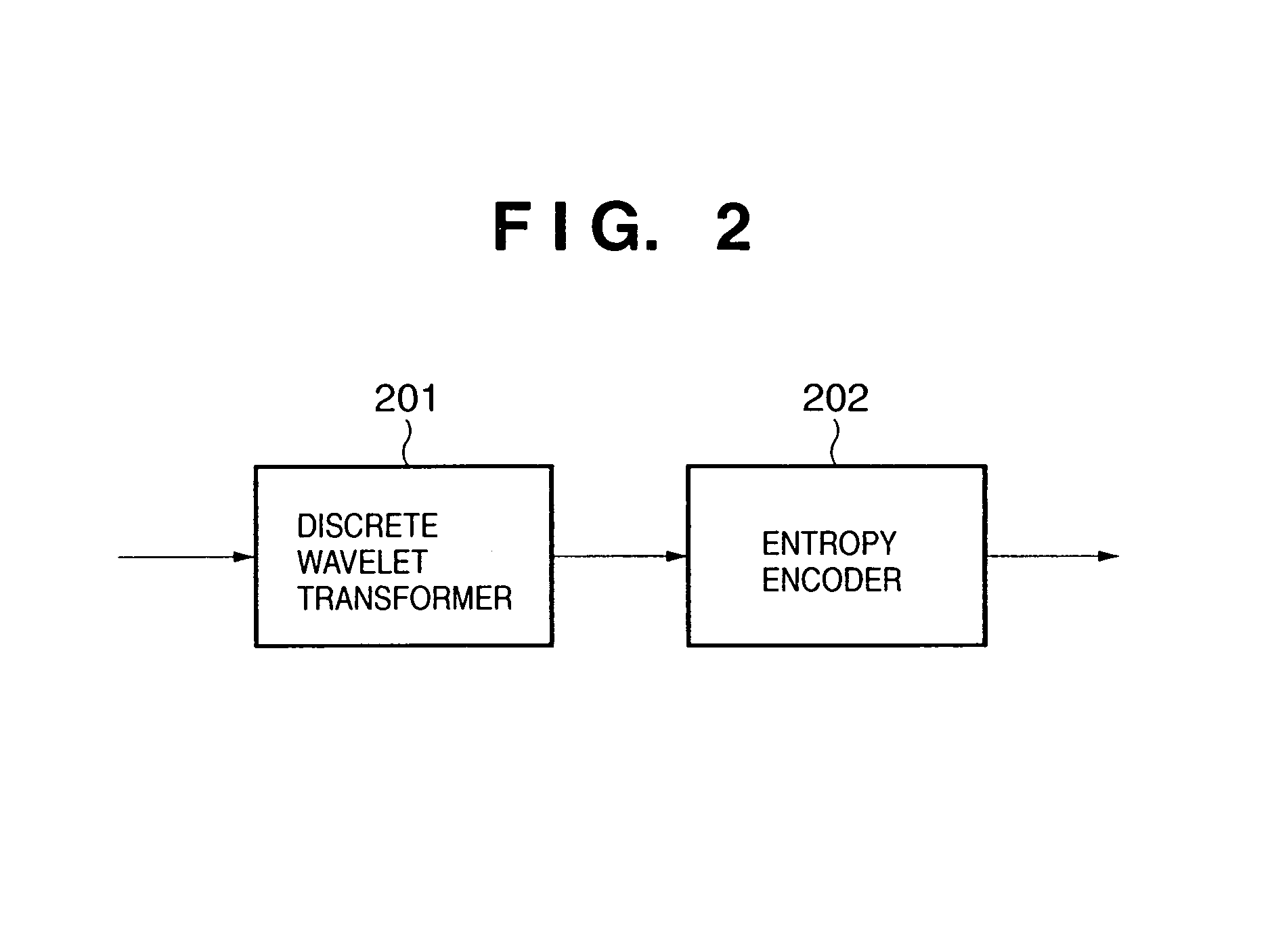
[0124]FIG. 13 shows an internal arrangement of the encoding device 2 according to this embodiment. An image signal input to the encoding device 2 undergoes discrete wavelet transformation in the discrete wavelet transformer 201 as in the first embodiment to generate transform coefficients. The generated transform coefficients are input to and quantized by a quantizer 203, and the obtained quantization indices are encode...


PUM


Abstract

Obtains an image from which noise is removed upon compressing or decoding and displaying an image containing noise. To accomplish this, a subband to which a wavelet transform coefficient of interest belongs is checked upon entropy decoding, and when the coefficient belongs to a subband other than LL, decoding is aborted at a predetermined lower-limit bit plane, and all bits contained in bit planes from the lower-limit bit plane to the least significant bit plane are set at zero.

Description

FIELD OF THE INVENTION[0001]The present invention relates to an image processing system and method for encoding / decoding an image.BACKGROUND OF THE INVENTION[0002]Many image compression coding techniques have been proposed since a storage medium having a very large size is required to save an image with high resolution and high pixel precision as a raw image.[0003]For example, a technique for saving / transferring X-ray medical images in an electronic format, and using them in diagnosis has been proposed. In the medical field, images preferably have highest possible resolution, and an effective image compression method is demanded.[0004]On the other hand, various techniques for canceling noise appearing in images have been proposed and are used in various fields.[0005]However, no technique for effectively reducing noise in the image encoding / decoding process has been proposed yet.[0006]For example, in an image sensing device using X-rays, the X-ray dosage upon image sensing is prefera...

Claims


Application Information

Patent Timeline
IPC IPC(8): G06K9/36H04N7/12G06T5/00G06T5/10G06T9/00
CPCG06T5/10G06T9/007G06T5/002G06T2207/30004G06T2207/10116G06T2207/20064G06T5/70
Inventor SATO, MAKOTOMATSUURA, TOMOHIKOSHINBATA, HIROYUKI
Owner CANON KK
Features
  • Generate Ideas
  • Intellectual Property
  • Life Sciences
  • Materials
  • Tech Scout
  • Unparalleled Data Quality
  • Higher Quality Content
  • 60% Fewer Hallucinations
Learn More