
Image heating apparatus having multiple rotatable members and temperature detecting element
- Summary
- Abstract
- Description
- Claims
- Application Information
AI Technical Summary
Benefits of technology
Problems solved by technology
Method used
Image

Examples
embodiment 2
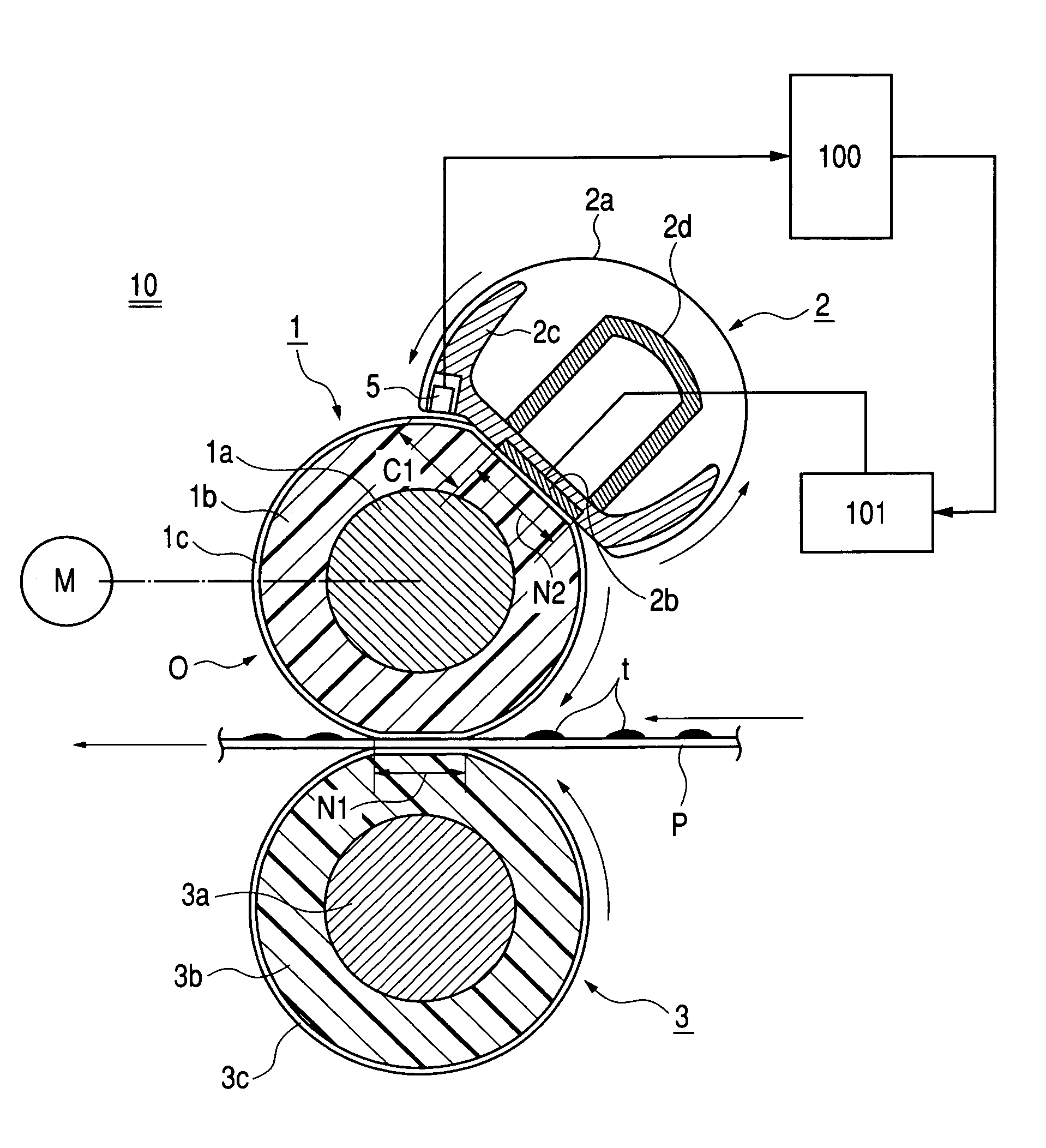
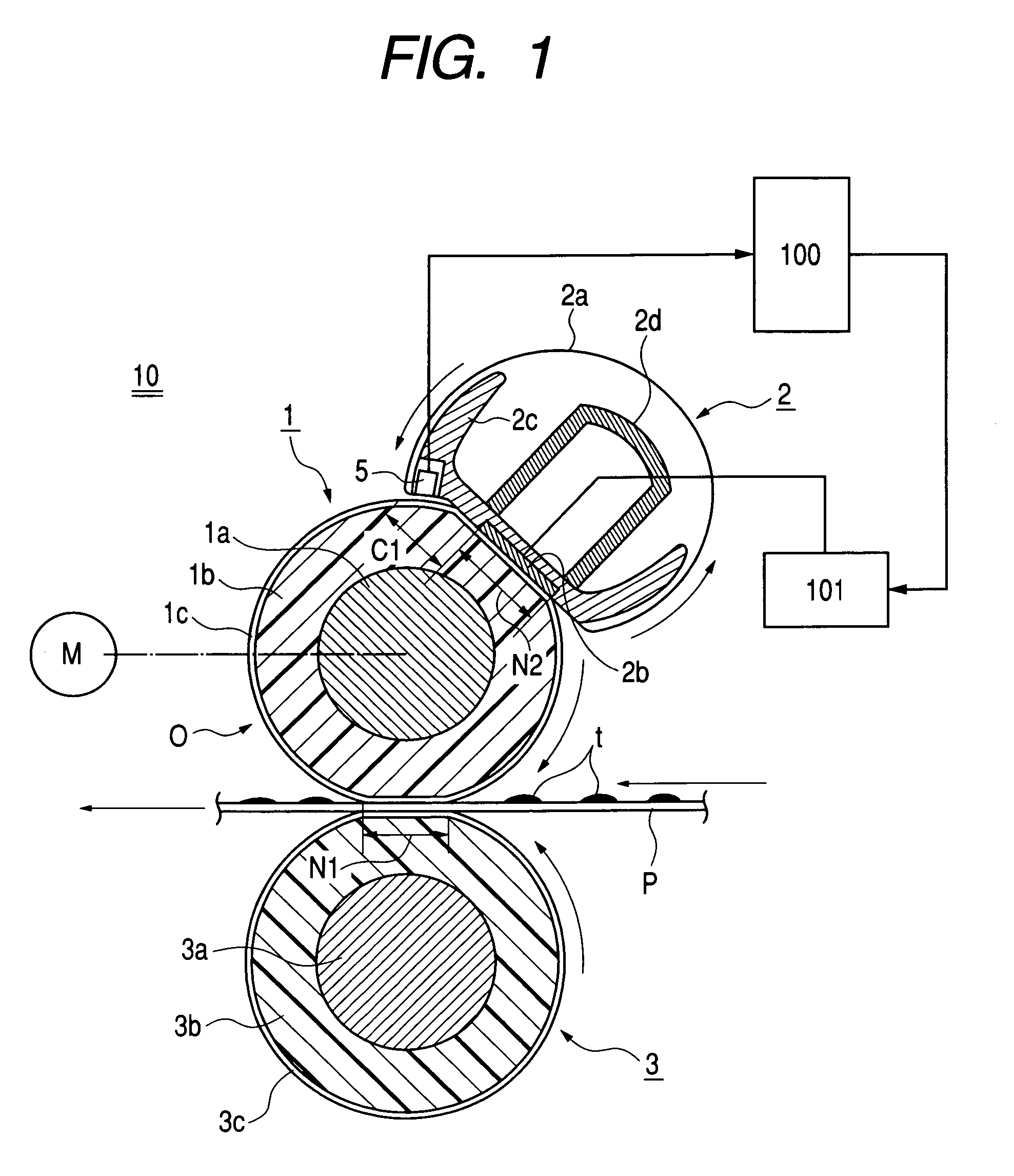
[0098]FIG. 8 is a partially cut away schematic diagram showing the fixing apparatus 10 according to an
[0099]The apparatus according to this embodiment is the same as the apparatus shown in FIGS. 1 to 6, 7A and 7B except for the position of the thermistor 5 as shown in FIG. 1.
[0100]That is, in the apparatus according to this embodiment, the heater holder 2c has a film guiding surface shaped so as to provide an extended film contact portion C2 for the heating film 2a to contact the fixing roller surface in an area downstream of the heater 2b (heating nip N2) in the direction of the rotation of the fixing roller. The heating film 2a is guided by the heater holder 2c so as to contact the fixing roller 1 at the heating nip N2 and the contact portion C2 downstream of the heating nip. And, in the extended film contact portion C2 of the surface heating unit 2, the thermistor 5 as temperature detecting means is provided in such a manner that it is constantly pressed by a spring or the like a...
embodiment 3
[0105]FIG. 9 is a partially cut away schematic diagram showing the fixing apparatus 10 according to an
[0106]The apparatus according to this embodiment is the same as the apparatus shown in FIGS. 1 to 6, 7A and 7B, except for the configuration of the surface heating unit 2′ as shown in FIG. 9.
[0107]The surface heating unit 2′ comprises a heating roller 2f, a halogen heater 2e contained in the heating roller 2f, a heating film 2a rotatably fitted onto the outer peripheral surface of the heating roller 2f, and a tension roller 2g for exerting a tension to the heating film 2a.
[0108]The heating roller 2f is a hollow cylinder made of aluminum having a thickness of 1 mm and a diameter of 30 mm. The halogen heater 2e has an output power of 700 W. The heating roller 2f abuts against the fixing roller 1 with the heating film 2a interposed therebetween to form the heating nip N2. The heating film 2a, the heating roller 2f and the tension roller 2g rotate by following the fixing roller 1.
[0109...
PUM
 Abstract
Description
Claims
Application Information