Injection quantity controller for an internal combustion engine

a technology of injection quantity controller and internal combustion engine, which is applied in the direction of electrical control, process and machine control, instruments, etc., can solve the problems of reducing learning accuracy, erroneous learning, and old data may not accurately reflect, so as to improve learning accuracy

Inactive Publication Date: 2006-01-10
DENSO CORP
View PDF6 Cites 9 Cited by
  • Summary
  • Abstract
  • Description
  • Claims
  • Application Information

AI Technical Summary

Benefits of technology

[0007]The present invention provides an injection quantity controller for an internal combustion engine that enhances learning accuracy by performing an injection quantity learning process with only data acquired within a predetermined period of time.

Problems solved by technology

However, even when utilizing the averaging method just described, old data may lead to erroneous learning or a reduction in learning accuracy.
This is true because the injection products tend to function differently with age and the old data may not accurately reflect the present injection quantity difference.

Method used


Image

  • Injection quantity controller for an internal combustion engine
  • Injection quantity controller for an internal combustion engine
  • Injection quantity controller for an internal combustion engine

Examples


first embodiment

[0036]FIG. 4 depicts a fuel injection system for a diesel engine configured in accordance with the principles of the present invention. The diesel engine includes a four-cylinder diesel engine (hereinafter referred to as an engine 1) having a fuel injection device.

[0037]The fuel injection device includes a common rail 2, a fuel pump 4, an injector 5, and an electronic control unit 6. The common rail 2 stores high-pressure fuel. The fuel pump 4 pressurizes fuel pumped from a fuel tank 3 and supplies it to the common rail 2. The injector 5 injects high-pressure fuel supplied from the common rail 2 to a cylinder (combustion chamber 1a) of the engine 1. The electronic control unit 6, hereinafter referred to as the ECU 6, controls the system.

[0038]The common rail 2 accumulates high-pressure fuel supplied by the fuel pump 4 to a target rail pressure that is set by the ECU 6. The common rail 2 includes a pressure sensor 7 and a pressure limiter 8. The pressure sensor 7 detects a fuel press...

second embodiment

[0084]FIG. 7 provides a second embodiment for checking the accumulated data in accordance with Step 170 of FIG. 5.

[0085]The checking process of the second embodiment is different from the first embodiment in that the ECU 6 returns to Step 171 after executing Step 175. Furthermore, the determination made by the ECU 6 in Step 171 is slightly different. Processing steps 172 to 174 are the same.

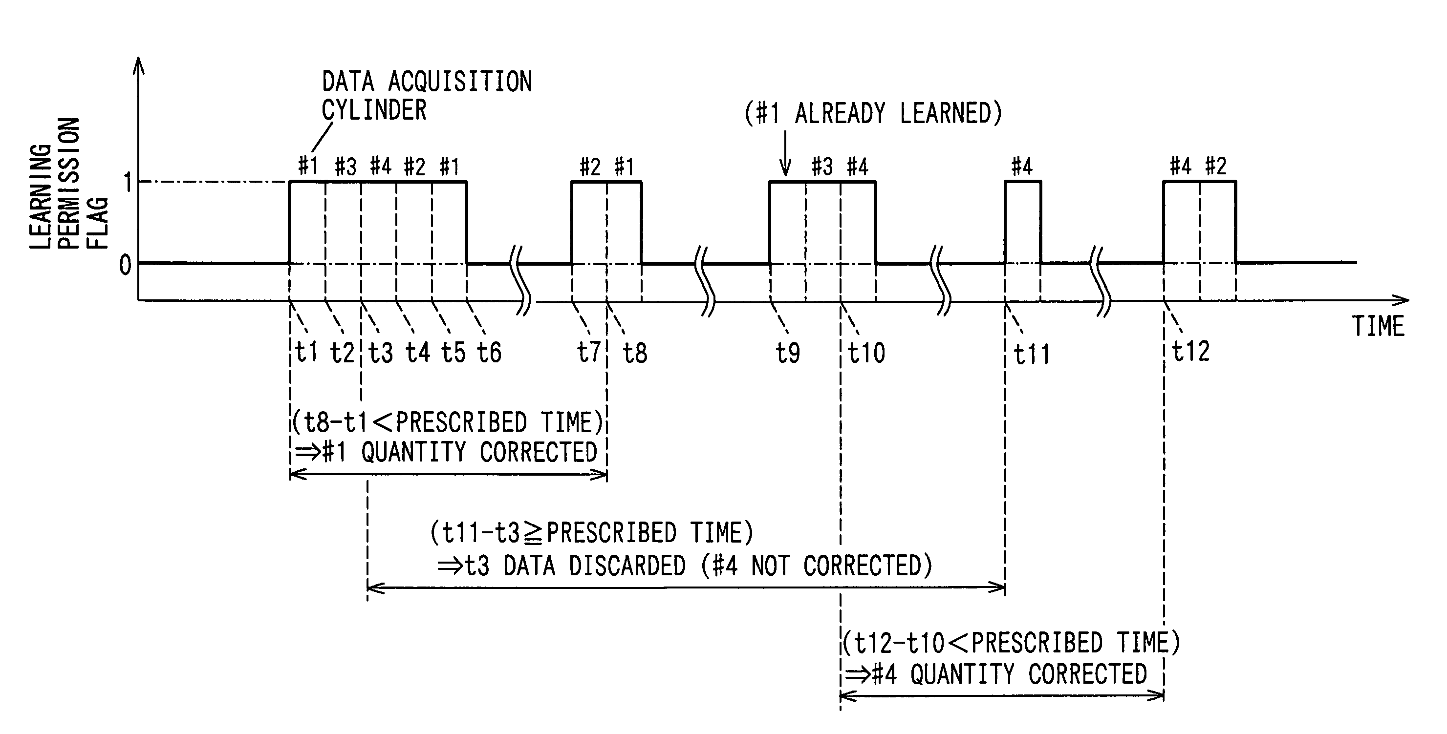
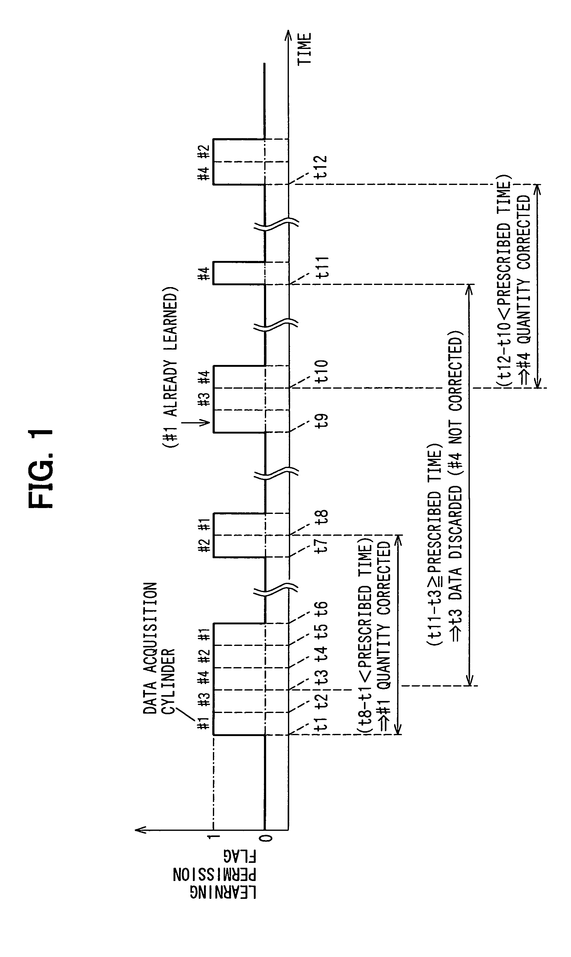
[0086]That is, the first embodiment, the ECU 6 checks the data when the number of pieces of accumulated data N(i) reaches the prescribed count N (Step 171: YES). However, in the second embodiment, the ECU 6 checks the data before the number of pieces N(i) reaches the prescribed count N and discards all data outside the prescribed time. Specifically, at step 171, the ECU 6 proceeds to calculating the time difference Δt when N(i) is greater than or equal to 2.

third embodiment

[0087]In the first embodiment, the ECU 6 does not correct the command injection quantity until a prescribed number N of pieces of data are acquired within the prescribed time. In a third embodiment, however, if the number of pieces of accumulated data is not greater than or equal to the prescribed count when the prescribed time lapses, the ECU 6 corrects the command injection quantity using the available data. Therefore, in FIG. 5, described above, Step 180 is eliminated in the third embodiment.

[0088]However, like the first embodiment, the ECU 6 of the third embodiment corrects the command quantity using only data acquired within the prescribed time. Any old data, which was acquired before the prescribed time, is discarded. Consequently, learning accuracy is enhanced.

[0089]It should be understood that in the third embodiment, the prescribed number of pieces of data to be accumulated within the prescribed time is not specified. Therefore, the ECU 6 corrects the command injection quan...


PUM


Abstract

The present invention performs an injection quantity learning process with only data acquired within a prescribed time. When the number of pieces of accumulated data reaches a prescribed count, a controller determines whether a time difference between when an oldest piece of data was acquired and when a latest piece of data was acquired is less than the prescribed time. When the difference is less than the prescribed time, the controller corrects a command quantity based on the prescribed number of pieces of data. According to this method, when the injection quantity is corrected, old data having been acquired before the prescribed time is discarded and the command quantity is corrected using only the prescribed number of pieces of data having acquired within the prescribed time, thereby enhancing learning accuracy.

Description

CROSS REFERENCE TO RELATED APPLICATION[0001]This application is based upon and claims the benefit of priority of Japanese Patent Application No. 2003-383898, filed Nov. 13, 2003, the contents of which are incorporated herein by reference.FILED OF THE INVENTION[0002]The present invention related to an injection quantity controller for an internal combustion engine that performs an injection quantity learning process to correct a difference between an actual injection quantity and a command injection quantity.BACKGROUND OF THE INVENTION[0003]Conventionally, pilot injection operations are performed on diesel engines to reduce combustion noise and Nox emissions. A pilot injection operation injects a minute quantity of fuel into a combustion chamber of the diesel engine prior to a main injection operation. However, for a pilot injection operation to have optimal effect (i.e., reduce combustion noise an Nox emissions), the accuracy of the quantity of the injection must be high.[0004]The p...

Claims


Application Information

Patent Timeline
Patent Type & Authority Patents(United States)
IPC IPC(8): F02D41/30F02D45/00F02D41/00F02D41/04F02D41/14F02D41/24F02D41/34F02D41/38
CPCF02D41/3827F02D41/2425F02D41/1497F02D41/008
Inventor ASANO, MASAHIROTAKEMOTO, EIJI
Owner DENSO CORP
Why Eureka
Try Eureka