Method of manufacturing and analyzing a composite building

a composite building and manufacturing technology, applied in nuclear engineering, nuclear elements, using mechanical means, etc., can solve the problems of insufficient proof, and insufficient use of buildings, so as to reduce energy consumption, reduce energy consumption, and easy assembly of materials

Inactive Publication Date: 2006-01-10
SAEBI NASSER
View PDF8 Cites 38 Cited by
  • Summary
  • Abstract
  • Description
  • Claims
  • Application Information

AI Technical Summary

Benefits of technology

[0011]It is another object of the invention to produce hoses that use easily assembled materials.
[0012]It is an object of the invention to provide a building that has a high insulation value to lower

Problems solved by technology

The fact that such buildings are not in wide use is not because they are inferior structures to houses built from wood.
Their scarcity is due to the fact that any new way of manufacturing buildings confronts the problem of proving to the various government organizations that such a house or building can meet the code requirements.
This proof is not easily or inexpensively done.
Many of the designs for foa

Method used


Image

  • Method of manufacturing and analyzing a composite building
  • Method of manufacturing and analyzing a composite building
  • Method of manufacturing and analyzing a composite building

Examples


Embodiment Construction

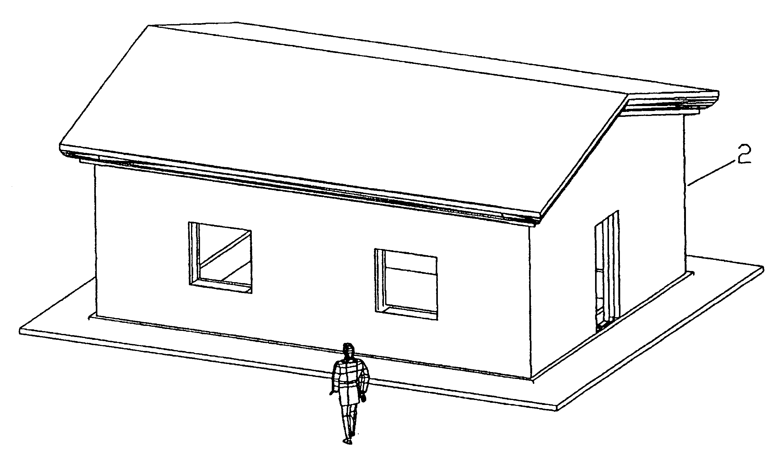
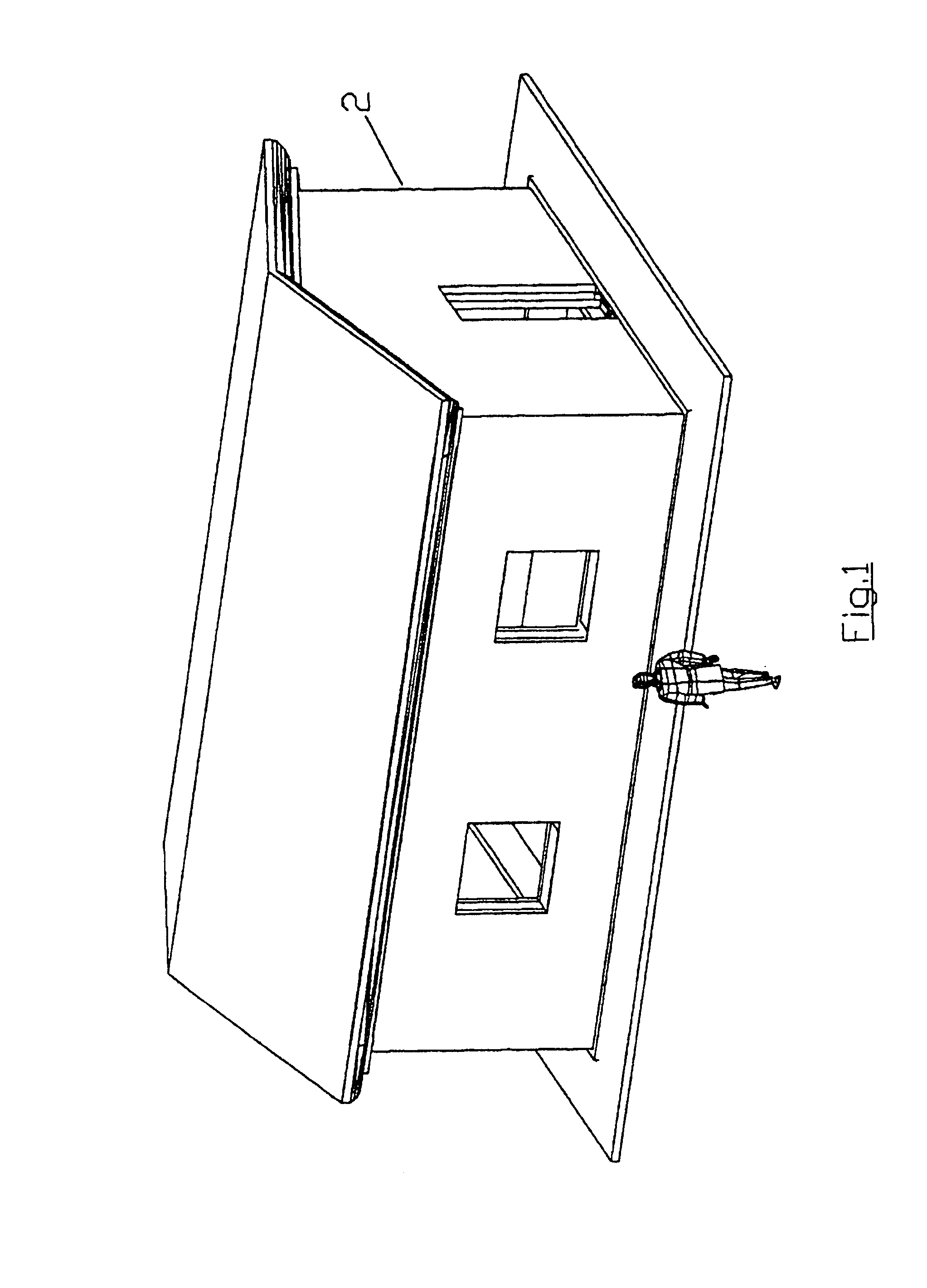
[0108]The manufacture or construction of the inventive building starts with the creation of a 3-Dimensional; “solid” model of the building in a computer assisted drafting (CAD) program in a computer. Suitable CAD programs are AutoCAD™, ProE™, Solid Works™, Inventor™, etc. The building is then sliced in parallel, usually vertical planes. These planes can correspond to various thicknesses of the slices, preferably of a size to be manhandled.

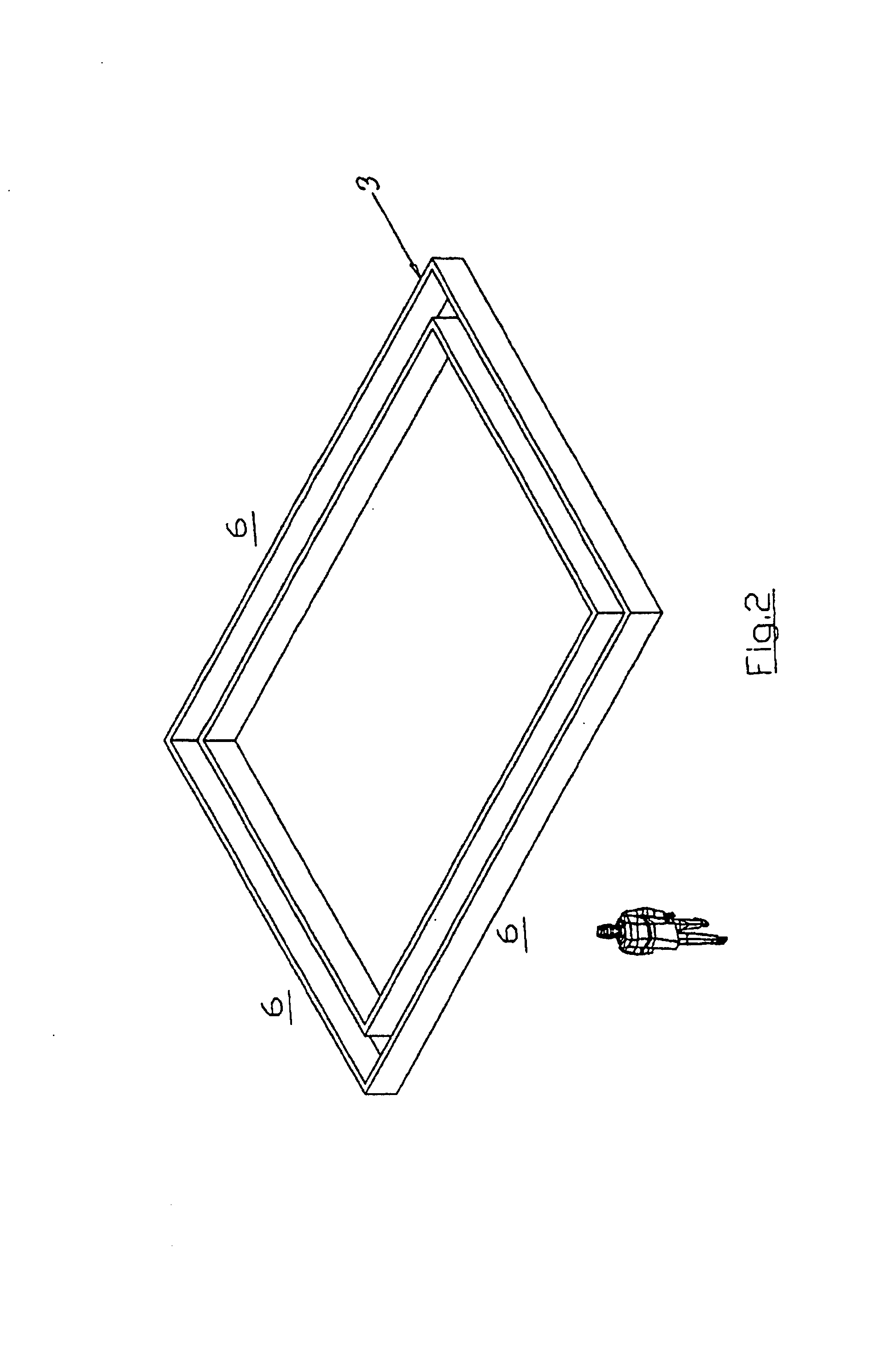
[0109]These slices of the building are then created by using foam, such as, expanded polystyrene (EPS). The foam elements that make up a slice can be cut from commercially available sizes of foam, such as slabs of 1 to 36 inches thick and 4 feet×8 feet or 4 feet×8 feet. The cutting can be performed by hand, machine or computer assisted manufacturing (CAM) program and a computer driven machine. The foam can be cut by hot wire or other suitable cutting process. The slice can be made by cutting elements which are then glued or otherwise joined togethe...


PUM


Abstract

The invention provides a method of manufacturing and analyzing a building made from Expanded PolyStyrene (EPS) which is coated on the inside and outside with Glass Fiber Reinforced Concrete (GFRC). The building is designed in a CAD program. Then, the building is divided up into small volumes in the CAD program or in a Finite Element Analysis program. Plates are added to the inner and outer surfaces of the volumes. Appropriate characteristics of the EPS and GFRC are assigned to the volumes and plates. A FEA analysis can then be run.

Description

CROSS-REFERENCE TO RELATED APPLICATIONS[0001]This application is a continuation of Ser. No. 10 / 132,915 filed Apr. 26, 2002, now U.S. Pat. No. 6,721,684 granted Apr. 13, 2004. This application is related to U.S. patent regular applications Ser. No. 09 / 563,142 filed May 2, 2000, now U.S. Pat. No. 6,308,490 granted Oct. 30, 2001 and Ser. No. 09 / 563,241 filed May 1, 2000 and is a continuation-in-part of provisional applications Ser. No. 60 / 287,240 filed Apr. 26, 2001 and Ser. No. 60 / 340,974 filed Nov. 29, 2001.[0002]In as far as possible, the disclosures of these applications are incorporated by reference in this application.BACKGROUND OF THE INVENTION[0003]The idea of a building formed of a composite of foam coated with concrete or cement started over fifty years ago. The fact that such buildings are not in wide use is not because they are inferior structures to houses built from wood. Their scarcity is due to the fact that any new way of manufacturing buildings confronts the problem o...

Claims


Application Information

Patent Timeline
IPC IPC(8): G06F15/00G06F11/30
CPCE04B1/167G06F17/5018G06F17/5004E04B2/847G06F30/13G06F30/23
Inventor SAEBI, NASSER
Owner SAEBI NASSER
Why Eureka
Try Eureka