System and method for distributing video information over network

a video information and network technology, applied in the field of video data distribution system and method, can solve the problems of limited number of client pcs, inconvenient use of existing lans, and low video compression ratio of intraframe coding

Inactive Publication Date: 2006-01-10
FUJITSU LTD
View PDF10 Cites 61 Cited by
  • Summary
  • Abstract
  • Description
  • Claims
  • Application Information

AI Technical Summary

Benefits of technology

[0014]Another object of the present invention is to provide a method which adaptively controls a process of delivering video information.

Problems solved by technology

However, most existing LANs are not suitable for the above-described usage because they are designed basically to transfer computer programs and data files, rather than to convey multimedia traffic which requires much wider bandwidths.
First, conventional techniques use connection-oriented communication services, the performance of which depends on total message traffic on the LAN being used.
For this reason, only a limited number of client PCs can make simultaneous access to the video source.
Another drawback is that intraframe coding provides too low video compression ratios.
In a network environment with a limited transmission bandwidth, insufficient compression would cause unnatural visual effects on the reproduced video, particularly in such a scene that includes rapid motions.
Because of this drawback, the conventional systems may not be able to satisfy the user requirements concerning picture quality.
Still another problem with the conventional systems may become apparent in such a situation where both high-performance PCs and low-performance PCs coexist on a single LAN environment.
High-performance PCs can decode and display video pictures at a high frame rate, taking advantage of their powerful CPUs, whereas low-performance PCs can only do the same job at limited rates because of their less-capable CPUs.
If a high rate video bitstream is broadcast to such non-uniform clients over the network, the low-performance PCs would only be able to reproduce poor video images, or in extreme cases, they would yield nothing.
However, this certainly shuts the high-performance PCs out of the chance to demonstrate their advantages.
In addition to indifference toward the above-described heterogeneity of PC clients in terms of video processing performance, the conventional video broadcasting techniques fail to provide effective measures to deal with transmission errors, which a client PC may encounter during the reception of a coded video stream.

Method used


Image

  • System and method for distributing video information over network
  • System and method for distributing video information over network
  • System and method for distributing video information over network

Examples


Embodiment Construction

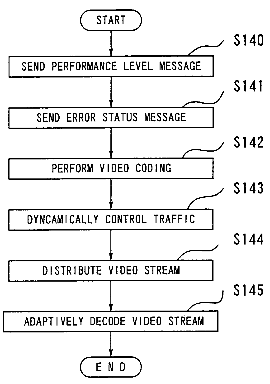
[0039]Preferred embodiments of the present invention will be described below with reference to the accompanying drawings.

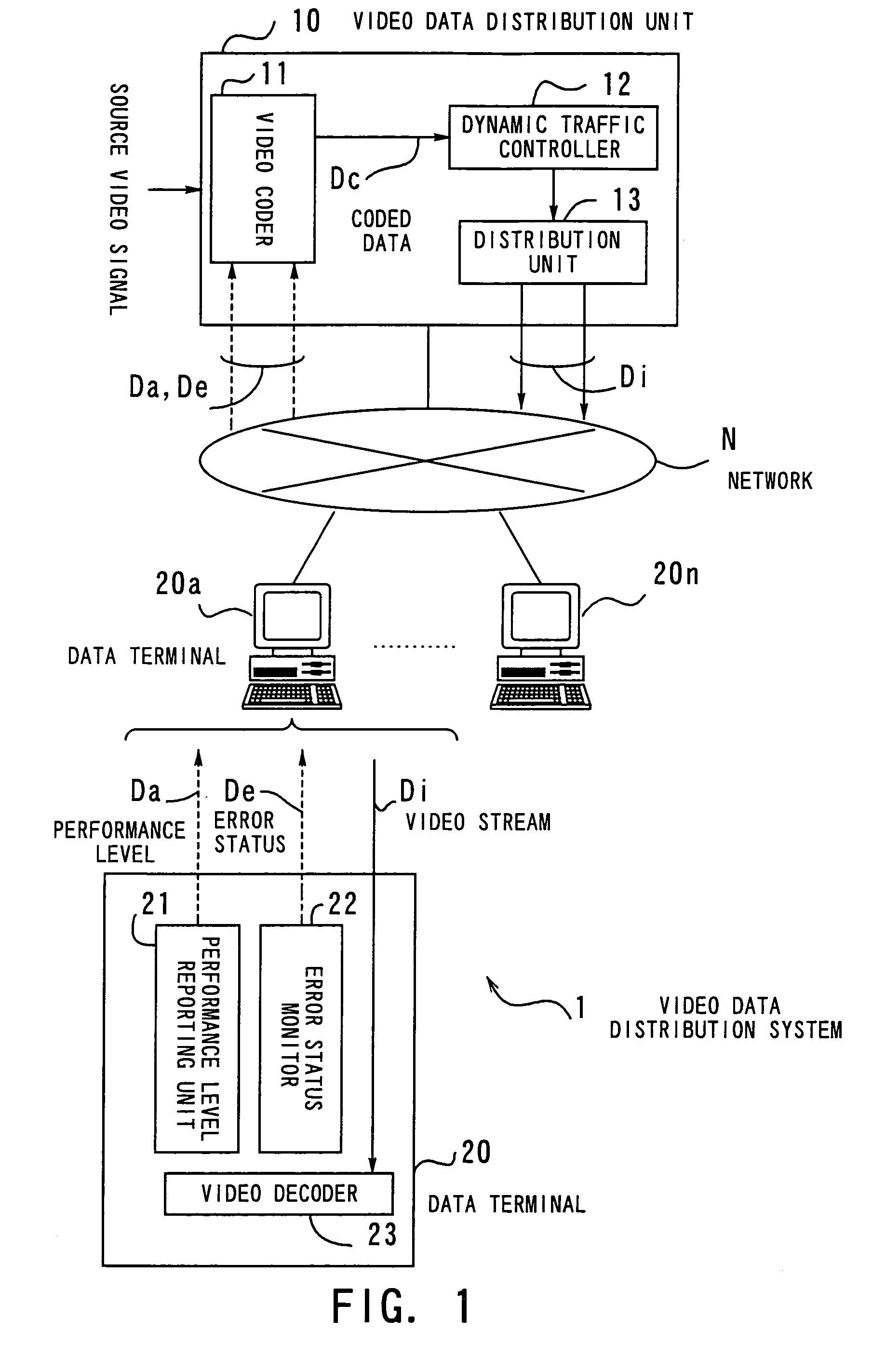
[0040]FIG. 1 shows the concept of a video data distribution system according to the present invention. This video data distribution system 1 comprises: a video data distribution unit 10 providing real-time multicast services of digital video data; a plurality of data terminals or personal computers 20a to 20n, and a network N interconnecting them. The system 1 controls delivery of video data over the network N, which is typically a local area network (LAN) or public switched telecommunications network.

[0041]The video data distribution unit 10 comprises: a video coder 11, a dynamic traffic controller 12, and a distribution unit 13. The video coder 11 produces coded data Dc by coding given source video signals on the basis of performance level messages Da and error status messages De sent from the data terminal 20a to 20n. The video coder 11 actually uses high compr...


PUM


Abstract

A system and method to adaptively control a process of distributing video information over a network. Each client data terminal subscribing to video services has a performance level reporting unit which sends a performance level message Da indicating what resources and computing power the terminal has. Each terminal also has an error status monitor which sends an error status message De. A video coder produces coded data Dc by coding source video signals, based on the received performance level messages Da and error status messages De. The traffic of this coded data Dc is dynamically varied by a dynamic traffic controller, and a distribution unit transmits the resultant video stream Di over the network, using IP multicasting techniques. A video decoder in each client terminal adaptively decodes the received video stream Di.

Description

BACKGROUND OF THE INVENTION[0001]1. Field of the Invention[0002]The present invention relates to a video data distribution system and method, and more particularly to a system and method for distributing video information to a plurality of client data terminals over a network.[0003]2. Description of the Related Art[0004]Remote video monitoring systems have been used to continuously watch one or more objects of interest for certain purposes, e.g., to protect environments or to detect a sign of natural disasters. Typically, dedicated central monitoring facilities equipped with multiple video monitor units are provided to enable centralized monitoring of target objects under observation.[0005]On the other hand, there are such demands that video images of remote objects be accessed through a network from locations other than the dedicated central facilities. This is motivated by the recent advancement of high-performance personal computers (PCs), which has made it possible for general u...

Claims


Application Information

Patent Timeline
Patent Type & Authority Patents(United States)
IPC IPC(8): H04N7/173H04N7/12H04N11/02H04N11/04G06F21/10H04N19/102H04N19/112H04N19/154H04N19/166H04N19/196H04N19/46H04N19/50H04N19/503H04N19/593H04N19/65H04N19/67H04N19/70H04N19/85H04N19/89H04N21/2343H04N21/24
CPCH04N21/2402H04N21/25808H04N21/658H04N21/6377H04N21/2662H04N21/4425H04N21/6582
Inventor TERUI, YUICHIANDOH, TOHRUHASEGAWA, MITSUYO
Owner FUJITSU LTD
Why Eureka
Try Eureka