Cab suspension device

Inactive Publication Date: 2006-01-17
VOLVO WHEEL LOADERS
View PDF9 Cites 25 Cited by
  • Summary
  • Abstract
  • Description
  • Claims
  • Application Information

AI Technical Summary

Benefits of technology

[0018]One advantage of the connecting means comprising an elongate member which connects the first element to the cab/vehicle frame is that the construction includes as few weaknesses and as little potential play as possible. By designing the elongate member with the same thread pitch at the upper end and the lower end, the connection can be adjusted (screwed) without the spacing between the first element and the cab/vehicle frame being changed, which is advantageous from the point of view of mounting. Among other things, a possibility is provided for mounting the invention from below the cab on occasions when it is difficult to reach from above. By, for example, first screwing the elongate member up into the cab with the aid of a nut stop and then mounting the first element in the vehicle frame, the connection can then be screwed down and adjusted in the first element. This may be particularly advantageous in the case of work with older machines which from the outset were not constructed for the type of suspensio

Problems solved by technology

Construction machinery/contractor's machinery such as, for example, wheel loaders and dumpers place considerable demands on the cab suspension construction.
A disadvantage of this type of construction is that “rubber collars” do not meet current high requirements for vibration insulation/vibration damping.
In most cases, the vibration-related and shock-related prevention characteristics are entirely adequate as far as elements of the “viscous mount” type are concerned, but the general problem is that strength characteristics are often limited.
The probl

Method used


Image

  • Cab suspension device
  • Cab suspension device
  • Cab suspension device

Examples


Embodiment Construction

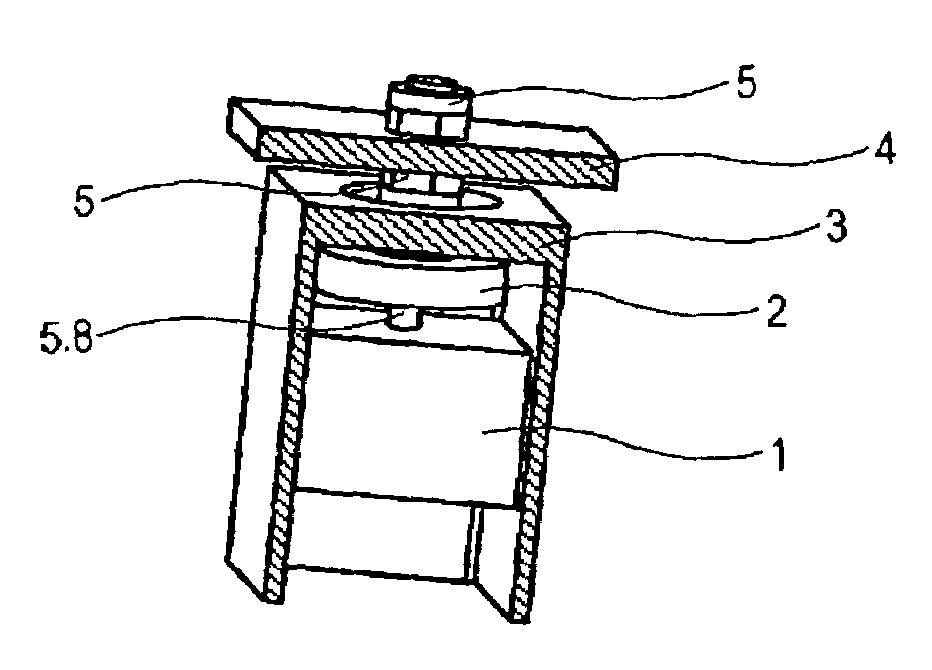
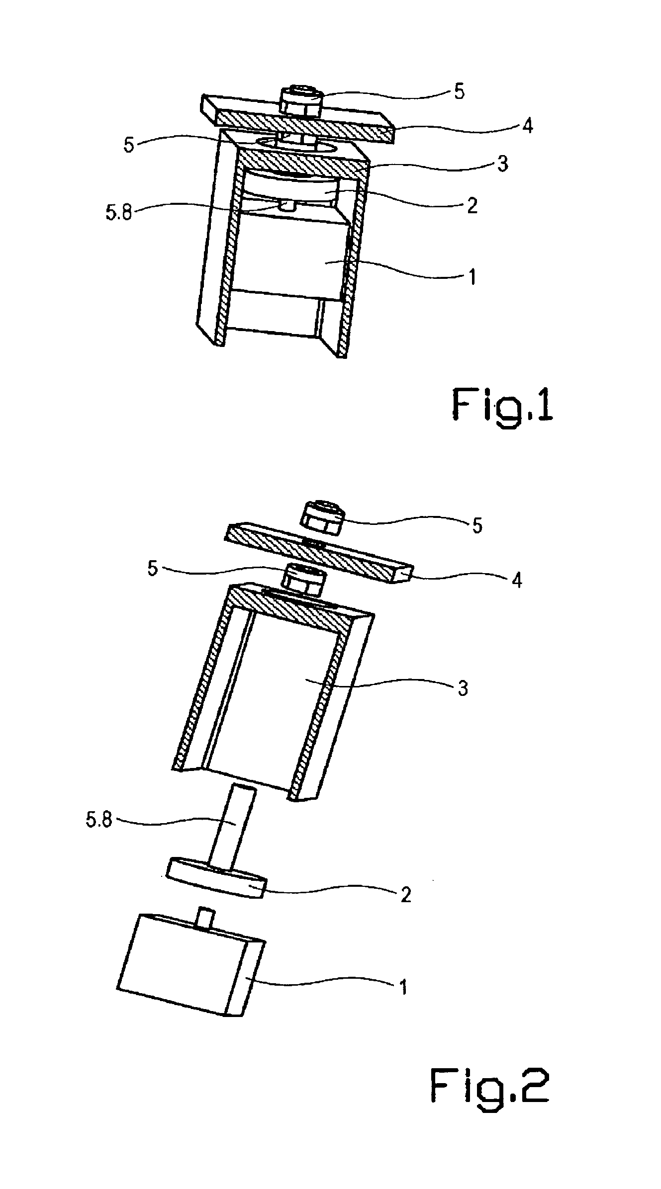
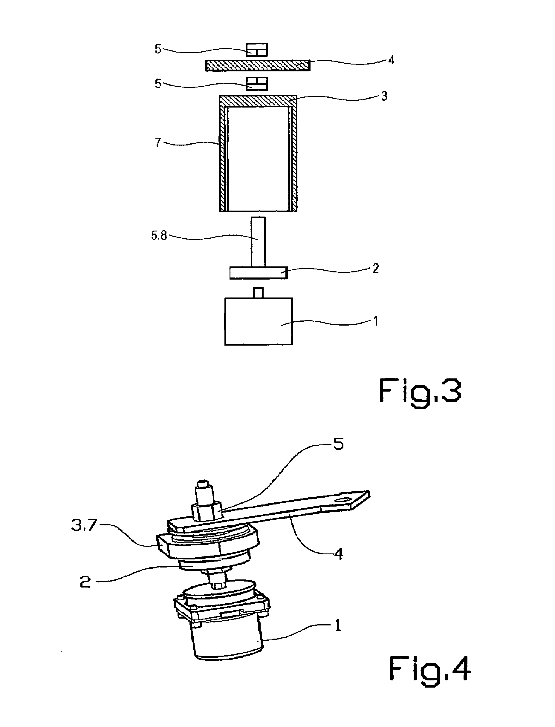
[0033]The figures below do not show a complete cab or vehicle frame, but these components are represented by small part-areas located close to the attachment points of the suspension device. Such a part-area may consist of, for example, part of a cab beam. The suspension of the cab normally comprises four suspension devices. The cab is positioned above the frame, and the vertical direction of the vehicle is essentially from the bottom up in the figures.

[0034]FIGS. 1, 2 and 3 show the principle of a first preferred embodiment of the invention. A first, vibration-damping element 1 is mounted firmly on a vehicle frame 3 by means of, for example, a screwed joint or a welded joint. With the aid of a connecting means 5, comprising an elongate member 8 and two nuts, the first element 1 is connected firmly to a cab 4, that is to say the first element 1 is connected firmly to the cab 4 via the connecting means 5. A second element 2, the element for taking up load, is arranged firmly on the e...


PUM


Abstract

Method and device for suspending a cab (4) on a vehicle frame (3) using vertical orientation for both a first element (1) that absorbs shocks/vibrations from the vehicle frame (3) to the cab (4) and a second element (2) that acts as a load support between cab (4) and the vehicle frame (3)in the event of, for example, accident situations. The first and second elements (1, 2) are arranged on the device, which connects the cab (4) to the vehicle frame (3) by a firm connection between the first element (1) and the cab (4), or alternatively the vehicle frame (3).

Description

CROSS REFERENCE TO RELATED APPLICATIONS[0001]The present application is a continuation patent application of International Application No. PCT / SE02 / 01229 filed 20 Jun. 2002 now abandoned, which was published in English pursuant to Article 21(2) of the Patent Cooperation Treaty, and which claims priority to Swedish Application No. 0102466-0 filed 9 Jul. 2001. Both applications are expressly incorporated herein by reference in their entireties.BACKGROUND OF INVENTION[0002]1. Technical Field[0003]The present invention relates to a device for suspension of a cab on a vehicle frame. The invention is intended in particular for construction machinery and contractor's machinery, the cab suspensions of which are subjected to relatively great stresses.[0004]2. Background Art[0005]Construction machinery / contractor's machinery such as, for example, wheel loaders and dumpers place considerable demands on the cab suspension construction. In order to make the working environment of the driver comf...

Claims


Application Information

Patent Timeline
IPC IPC(8): B62D33/10B62D33/067B62D27/04B62D33/06F16F15/02
CPCB62D33/0604B62D33/06
Inventor NILSSON, INGEMARERICSSON, ALLANLINDBLOM, JONNYNORLING, LEIFFORNELL, MAGNUS
Owner VOLVO WHEEL LOADERS
Why Eureka
Try Eureka