Method of endovenous laser treatment

a laser treatment and endovenous technology, applied in the field of endovenous laser treatment, can solve the problems of unsatisfactory methods, unsuitable inserting of optical fiber directly into body tissue, and so as to minimize the length of optical fiber remaining, prevent thermal damage to the introducer sheath, and facilitate the effect of marking

Inactive Publication Date: 2006-01-17
ANGIODYNAMICS INC +1
View PDF24 Cites 76 Cited by
  • Summary
  • Abstract
  • Description
  • Claims
  • Application Information

AI Technical Summary

Benefits of technology

[0019]The first and second markings allow an operator or surgeon to know when the distal end of the optical fiber is aligned with the end of the introducer sheath and when the distal end of the optical fiber extends beyond the introducer sheath by a predetermined amount. This enables the operator or surgeon to quickly insert the optical fiber into the introducer sheath and enables the optical fiber to be positioned in the optimum position relative to the introducer sheath without risk of damage to either the optical fiber or surrounding tissue.
[0022]The minimum preferred separation (2 cm) is so as to prevent thermal damage to the introducer sheath during treatment. The maximum preferred separation (4 cm) is so as to minimize the length of the optical fiber remaining within the body once the introducer sheath has been removed from the patient's body.
[0023]The two markings or markers may differ in shape and color to aid the operator or surgeon using the device. This can make it easier to refer to the markings, for example, when teaching or explaining how to use the device to another operator or surgeon.
[0024]The markings may be engraved or embossed on the optical fiber. This enables the operator to have tactile feedback as to the position of the markings, without having to look at the optical fiber. This allows the operator to concentrate on other equipment. Furthermore, if the markings are embossed then there may be sufficient co-operation between the marking and a friction seal of the introducer sheath so as to secure them temporarily together when the introducer sheath is retracted.
[0027]The optical fiber is preferably secured to the introducer sheath at a position wherein the first marking is substantially in alignment with the proximal end of the introducer sheath. The optical fiber and the introducer sheath may then be positioned at a desired location using ultrasound. The introducer sheath can then be released from the optical fiber and the introducer sheath withdrawn relative to the fiber optic device until the second marking in substantially in alignment with the proximal end of the introducer sheath, enabling the distal end of the optical fiber to protrude a known distance from the distal end of the introducer sheath in order to administer laser energy. The optical fiber may then be secured to the introducer sheath substantially at the position where the second marking is substantially in alignment with the proximal end of the introducer sheath, and energy from a laser energy source may then be provided to the distal end of the optical fiber. The optical fiber and the introducer sheath may be withdrawn whilst laser energy is emitted from the distal end of the optical fiber. This is an advantageous way of administering laser energy invasively.

Problems solved by technology

However, the tips of such optical fibers could cause trauma to soft tissues.
Therefore, for some invasive applications it is not desirable to insert the optical fiber directly into the body tissue.
However, these methods are unsatisfactory for a number of reasons.
The use of ultrasound requires additional equipment which is expensive and complicates the procedure.
Therefore, conventional techniques are not suitable for use in a wide range of applications.
Furthermore, as a result of it being difficult for an operator or surgeon to determine when the distal end of the optical fiber is approaching the distal end of the introducer sheath, damage can readily occur to the soft tissues if the optical fiber is initially accidentally extended beyond the introducer sheath.

Method used


Image

  • Method of endovenous laser treatment
  • Method of endovenous laser treatment
  • Method of endovenous laser treatment

Examples


Embodiment Construction

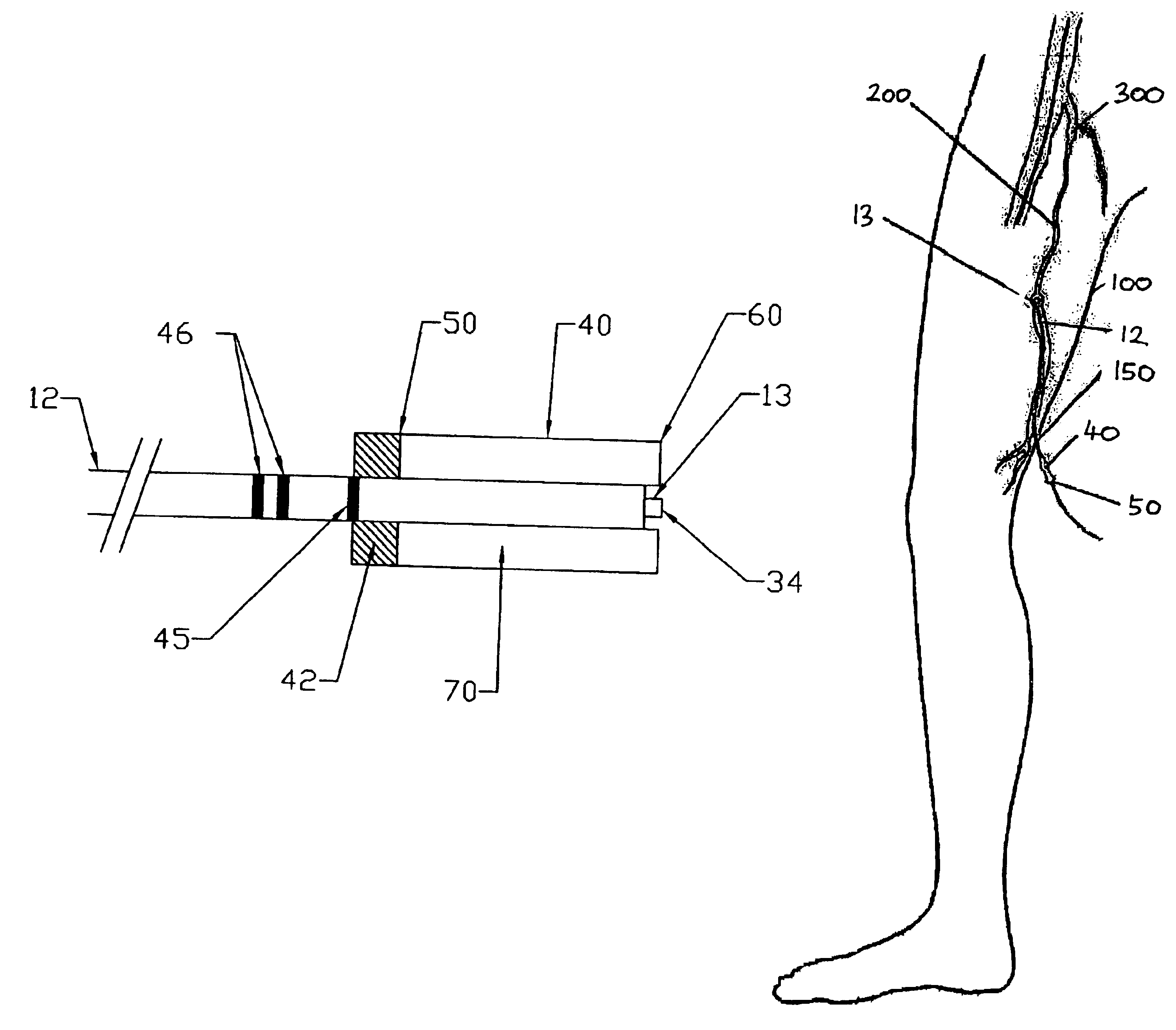
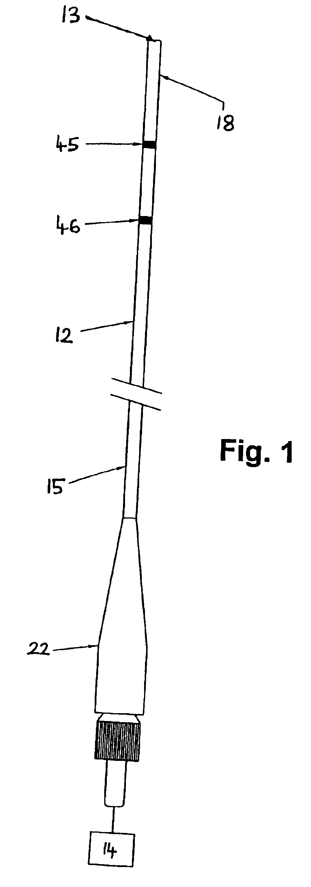
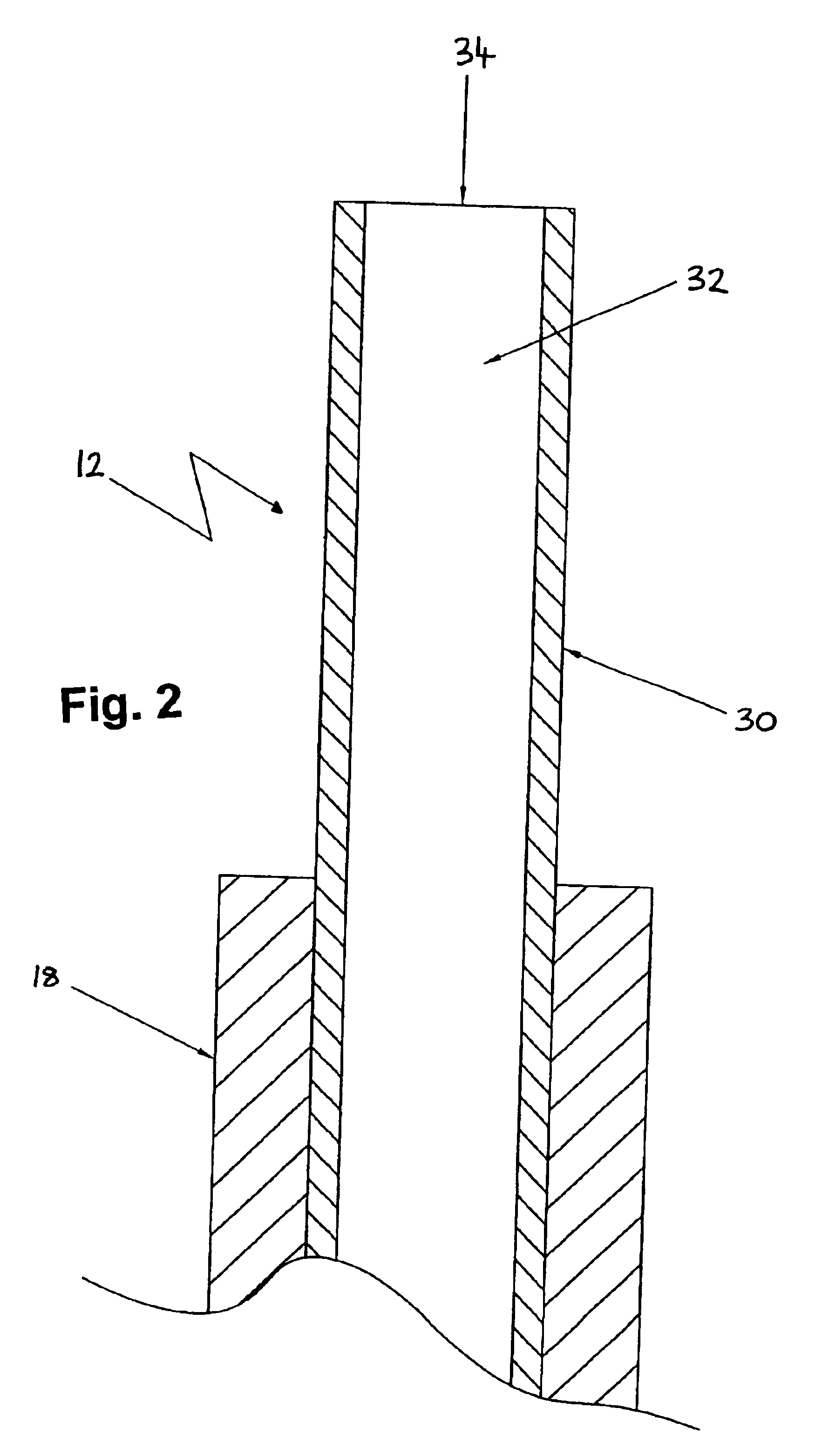
[0053]With reference to FIGS. 1 and 2, an optical fiber 12 having a distal end 13 and a proximal and 15 is shown which is coupled to a laser energy source 14 via a connector 22. According to one embodiment the optical fiber 12 has a length of 3.5 m±0.1 m and is preferably provided with a protective buffer layer 18. One or mare markings or other form of indicator 45, 46 are arranged on the optical fiber 12 at a predetermined distance from distal end 13. Preferably, the markings 45, 46 are provided around substantially the whole circumference of the protective buffer layer 18 of the optical fiber 12. According to the preferred embodiment, the laser energy source 14 is an 810 nm diode laser manufactured by DIOMED, Ltd., United Kingdom. The connector 22 may be any suitable connector / fiber terminator such as a standard sub-miniature A (SMA) connector (as shown) or other proprietary connector.

[0054]The distal end 13 of the optical fiber 12 is shown in more detail in FIG. 2. The optical fi...


PUM


Abstract

A method of endovenous laser treatment in disclosed. An introducer sheath 40 is introduced into a vein and an optical fiber 12 is introduced through the introducer sheath until a first marking 45 on the optical fiber 12 indicates that the distal end of the optical fiber 12 is substantially in alignment with the distal end of the introducer sheath 40. The introducer sheath 40 is then withdrawn relative to the optical fiber 12 until a second marking 46 on the optical fiber 12 indicates that the distal end of the optical fiber 12 extends a predetermined distance beyond the distal end of said introducer sheath 40. Laser radiation is passed down the optical fiber 12 so that laser radiation is delivered to the inner wall of the vein and the introducer sheath 40 together with the optical fiber 12 are withdrawn a certain distance along the vein.

Description

CROSS-REFERENCE TO RELATED APPLICATIONS[0001]This application claims priority from U.S. Provisional Patent Application Ser. No. 60 / 369,256, filed Mar. 27, 2002. and from UK Patent Application Serial No. GB-0114687, filed Jun. 15, 2001, the entire contents of each application being hereby incorporated herein by reference.BACKGROUND OF THE INVENTION[0002]1. Field of the Invention[0003]The present invention relates to a method of endovenous laser treatment.[0004]2. Description of the Related Art[0005]In certain invasive medical procedures thermal or other energy is administered to a patient with beneficial effects. For example, energy can be used to detect a tumour or a region of the body, or to destroy or denature diseased or malfunctioning body tissue. One example of this type of treatment is disclosed in U.S. Pat. No. 6,095,149 which describes the treatment of invertebral disc abnormalities with thermal energy. Other types of medical treatment utilise laser energy, for example endov...

Claims


Application Information

Patent Timeline
Patent Type & Authority Patents(United States)
IPC IPC(8): A61B18/18A61B18/22A61B19/00
CPCA61B18/22A61B2019/5437A61B2019/462A61B2090/062A61B2090/3937
Inventor CALDERA, TIZIANOMIN, ROBERTKLEIN, PETER
Owner ANGIODYNAMICS INC
Why Eureka
Try Eureka