Test photomask, flare evaluation method, and flare compensation method

a technology of flare compensation and photomask, which is applied in the field of flare compensation method and flare evaluation method, can solve the problems of no preferred technique, unintended change in the shape and line width of the pattern to be transferred,

Inactive Publication Date: 2006-01-17
FUJITSU SEMICON LTD
View PDF6 Cites 15 Cited by
  • Summary
  • Abstract
  • Description
  • Claims
  • Application Information

AI Technical Summary

Benefits of technology

[0008]The present invention is developed to solve the above-described problem and it is an object thereof to provide a test photomask for quantitatively estimating the effect of local flare on a pattern which is exposed in lithography, and a flare evaluation method using the same.

Problems solved by technology

However, flare, which locally occurs depending on an exposure pattern due to a lens material associated with such a short wavelength, comes to be seen as a problem.
This is so-called local flare that becomes a main cause of unintended change in the shape and the line width of a pattern to be transferred.
The local flare, however, is a problem that has recently been focused on as described above, and thus, in the present circumstances, no preferable technique has been supposed yet for intentionally solving the problem giving an attention to the local flare.

Method used


Image

  • Test photomask, flare evaluation method, and flare compensation method
  • Test photomask, flare evaluation method, and flare compensation method
  • Test photomask, flare evaluation method, and flare compensation method

Examples


modified examples

[0063]Now, various modified examples of the first embodiment will be described. These examples disclose techniques of quantitatively evaluating local flare as in the first embodiment, but are different therefrom in the test photomask. Note that components and so on corresponding to those in the first embodiment are designated the same reference numerals, and description thereof is omitted.

modified example 1

[0064]FIGS. 7A to 7D are schematic diagrams showing the general configuration of a test photomask which is a component of a flare evaluating apparatus according to the modified example 1 of the first embodiment.

[0065]A test photomask 21 is constituted by, as shown in FIG. 7A, a pair of photomasks 21a and 21b in which the photomask 21a is formed with a line pattern group 22, and the photomask 21b is formed with a zone pattern group 23 respectively.

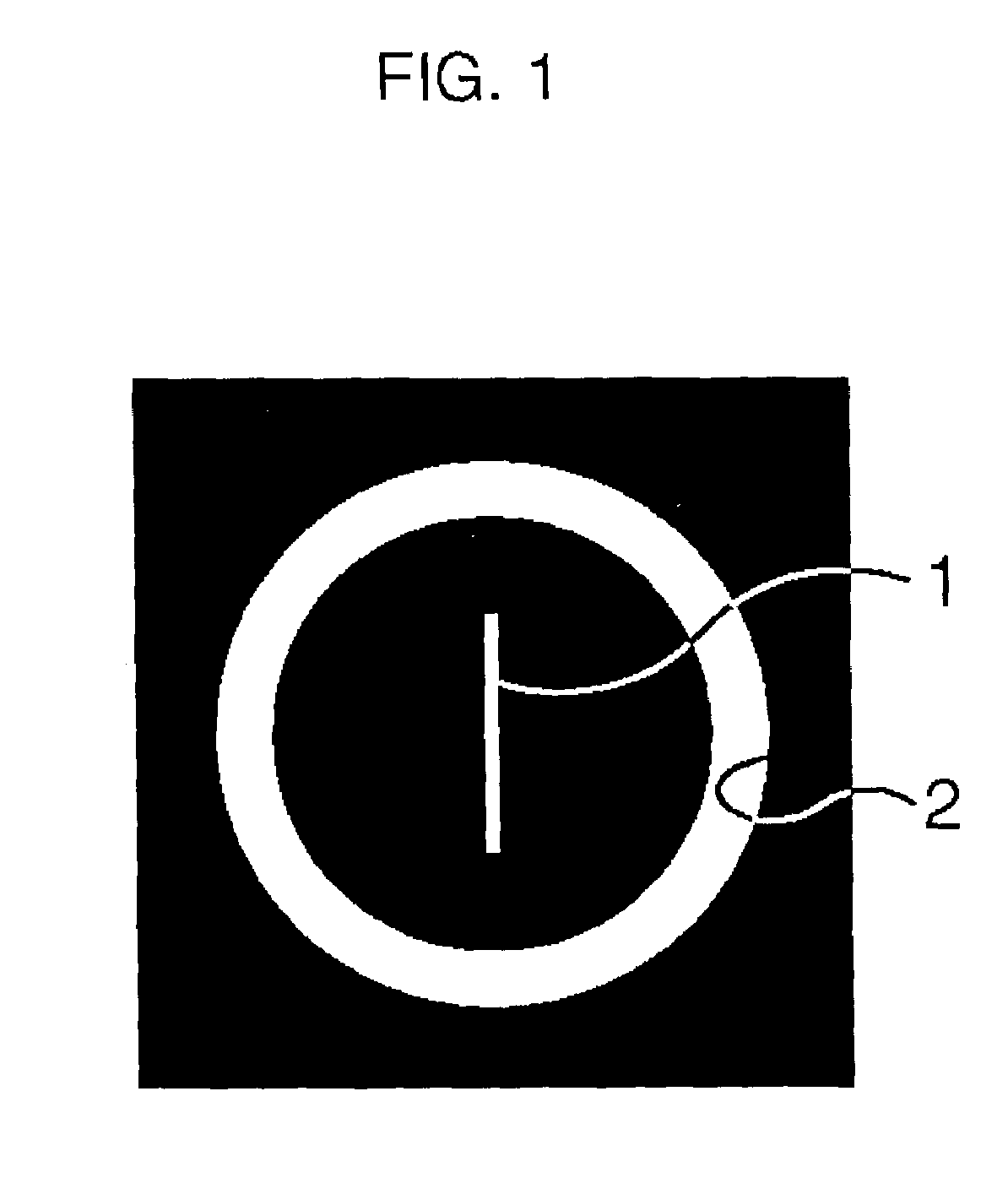
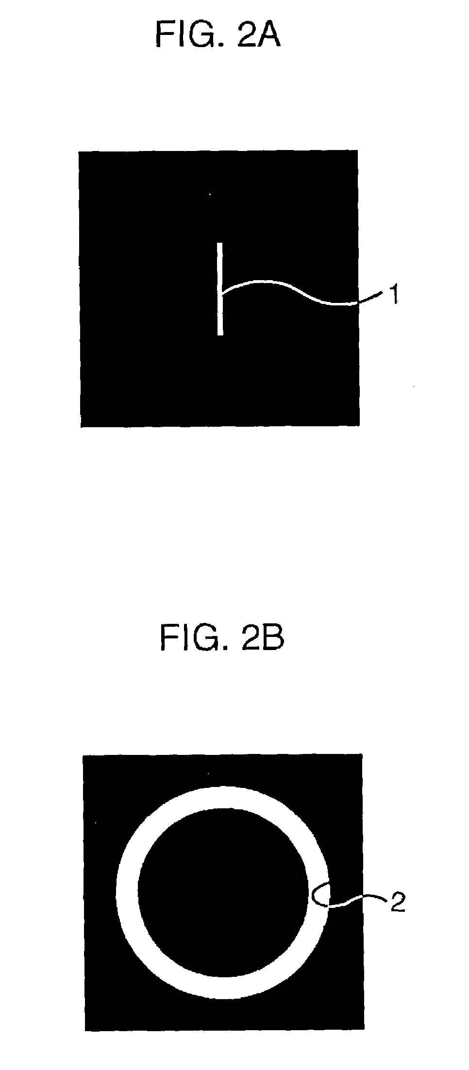
[0066]In the line pattern group 22, as shown in FIG. 7B, only a plurality of line patterns 1 are formed apart from each other to such an extent as not to be affected by local flare. In the zone pattern group 23, as shown in FIG. 7C, only a portion formed with no pattern (shown at the uppermost position) and zone patterns 2 which are sequentially increased in inside diameter and outside diameter, are formed adjacent to each other. The relation in size between the zone patterns 2 is similar to that in FIGS. 4A to 4D. The line pattern group 22...

modified example 2

[0071]FIGS. 8A to 8D are schematic diagrams showing the general configuration of a test photomask which is a component of a flare evaluating apparatus according to a modified example 2 of the first embodiment.

[0072]A test photomask 31 is constituted, as shown in FIG. 8A, by one photomask in which a line pattern group 32 and a zone pattern group 33 are formed apart enough from each other to such an extent as not to be affected in exposure.

[0073]In the line pattern group 32, as shown in FIG. 8B, only a plurality of line patterns 1 are provided apart from each other to such an extent as not to be affected by local flare. In the zone pattern group 33, as shown in FIG. 8C, only a portion formed with no pattern (shown at the uppermost position) and zone patterns 2 which are sequentially increased in inside diameter and outside diameter, are provided apart from each other to such an extent as not to be affected by local flare. The relation in size between the zone patterns 2 is similar to ...


PUM

PropertyMeasurementUnit
wavelengthaaaaaaaaaa
diameteraaaaaaaaaa
diameteraaaaaaaaaa

Abstract

Through use of a line pattern which becomes a pattern under measurement and a zone pattern in a zonal shape which becomes a flare causing pattern forming a light transmission region which surrounds the line pattern and causes local flare to occur on the line pattern, the effect of the local flare due to the zone pattern on the line pattern is measured as a line width of the line pattern for evaluation. Further, this measurement value is used to compensate the effect of the local flare on each real pattern.

Description

CROSS-REFERENCE TO RELATED APPLICATIONS[0001]This application is based upon and claims the benefit of priority from the prior Japanese Patent Application No. 2002-223966, filed on Jul. 31, 2002, the entire contents of which are incorporated herein by reference.BACKGROUND OF THE INVENTION[0002]1. Field of the Invention[0003]The present invention relates to a flare evaluation method, a flare compensation method, and a test photomask for an aligner used in a lithography process that is one of manufacturing processes of a semiconductor device.[0004]2. Description of the Related Art[0005]In recent years, a projecting aligner of a dioptric system or catadioptric system is used when forming patterns in a semiconductor element, in which light in an optical path different from the designed one is generated because of reflection and scattering on the surface and inside of a lens of an illumination optical system, a mask, a projection lens, and so on and unevenness in refractive index of lens ...

Claims


Application Information

Patent Timeline
Patent Type & Authority Patents(United States)
IPC IPC(8): G03F9/00G03F1/36G03F1/68G03F1/70G03F7/20H01L21/027
CPCG03F7/70941G03F7/70591G03F7/20H01L21/027
Inventor YAO, TERUYOSHIHANYU, ISAMUKIRIKOSHI, KATSUYOSHI
Owner FUJITSU SEMICON LTD
Why Eureka
Try Eureka