Self-contained locking trigger assembly and systems which incorporate the assembly

a self-contained, trigger technology, applied in the field of welding systems, can solve the problems of time-consuming and labor-intensive assembly of the trigger and the trigger lock pieces with the handle, and the possibility of failure of the trigger and the trigger lock is greater

Inactive Publication Date: 2006-01-17
ILLINOIS TOOL WORKS INC
View PDF8 Cites 220 Cited by
  • Summary
  • Abstract
  • Description
  • Claims
  • Application Information

AI Technical Summary

Problems solved by technology

Assembling the trigger and trigger lock pieces together with the handle may be time-consuming.
Additionally, the more the various individual pieces are required to cooperate, the greater the possibility of failure of the trigger and trigger lock.

Method used


Image

  • Self-contained locking trigger assembly and systems which incorporate the assembly
  • Self-contained locking trigger assembly and systems which incorporate the assembly
  • Self-contained locking trigger assembly and systems which incorporate the assembly

Examples


Embodiment Construction

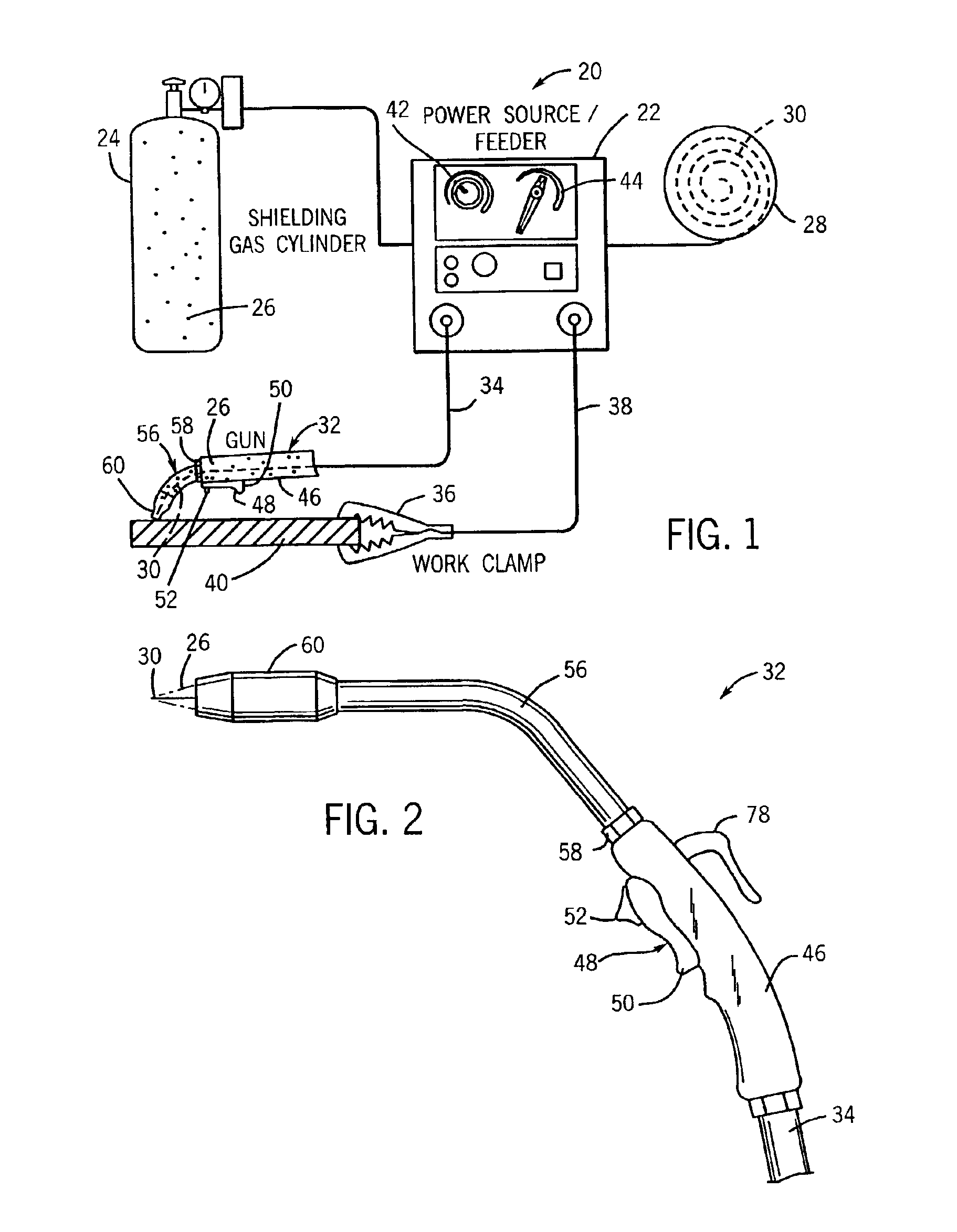
[0019]Referring generally to FIG. 1, an exemplary metal inert gas (“MIG”) welding system 20 is illustrated. However, the present technique is operable with other types of welding systems, such as submerged arc welding systems. The illustrated welding system 20 comprises a power source / wire feeder 22, a gas cylinder 24 containing a gas 26 that is coupled to the power source / wire feeder 22, a spool 28 of electrode wire 30 that is coupled to the power source / wire feeder, a welding gun 32 having a welding cable 34, a work clamp 36, and a ground cable 38. However, the present techniques are applicable to welding implements other than a welding gun. In the illustrated embodiment, the power source and wire feeder are combined. However, the power source and wire feeder may also be provided as separate welding devices.

[0020]The power source / wire feeder 22 provides electric power to the welding gun 32 via the welding cable 34. Additionally, the power source / wire feeder 22 directs the feeding ...


PUM

PropertyMeasurementUnit
electrical resistanceaaaaaaaaaa
electric currentaaaaaaaaaa
currentaaaaaaaaaa

Abstract

A welding system having a welding implement with a self-contained trigger and trigger locking assembly. The self-contained trigger and trigger locking assembly has a trigger which, when operated, regulates the flow of current from a power source. The trigger lock of the assembly has a movable portion which includes a groove which can engage a complementary structure on the trigger to maintain the trigger in an operating position, thereby allowing continued flow of current from the power source.

Description

CROSS REFERENCE TO RELATED APPLICATIONS[0001]This patent application is a continuation-in-part of patent application Ser. No. 10 / 210,638, filed Jul. 31, 2002, entitled, “Welding System Having Welding Gun With Self-Contained Locking Trigger.”BACKGROUND OF THE INVENTION[0002]The present invention relates generally to welding systems, and particularly to a welding system having a welding implement coupled to a source of electric power. In particular, one aspect of the present invention relates to a self-contained trigger and trigger lock assembly which may be incorporated into a welding implement[0003]Welding is a method of joining pieces of metal together into one solid piece. Welding implements are used in a number of different types of welding. For example, welding implements are typically used in arc welding. An arc welding system typically comprises an electric power supply coupled to a welding implement that houses an electrode. The electric power supply typically includes a cond...

Claims


Application Information

Patent Timeline
Patent Type & Authority Patents(United States)
IPC IPC(8): B23K9/00B23K9/10B23K9/173B23K9/29B23K9/32
CPCB23K9/10B23K9/1006B23K9/32B23K9/295B23K9/173
Inventor BAUER, GREGORY W.
Owner ILLINOIS TOOL WORKS INC
Why Eureka
Try Eureka