
Apparatus and method for generating multi-phase signals with digitally controlled trim capacitors

a technology of digital control and trim capacitor, applied in the direction of electrical apparatus, pulse automatic control, etc., can solve the problems of large area filter capacitor, high implementation cost, and large voltage source, and achieve the effect of providing linear response and minimizing signal dri

Inactive Publication Date: 2006-01-17
ARM FINANCE OVERSEAS LTD
View PDF5 Cites 9 Cited by
  • Summary
  • Abstract
  • Description
  • Claims
  • Application Information

AI Technical Summary

Benefits of technology

[0015]Thus, the invention provides a digital control circuit to generate digital signals that control trim capacitors associated with a delay chain. The digital design is fast, inexpensive, and provides a linear response. The design is insensitive to noise and is otherwise robust. Advantageously, the system clock is used to track the accuracy of the multi-phase signals generated by the design; therefore, the design minimizes signal drift.

Problems solved by technology

Unfortunately, these approaches are expensive to implement for two reasons.
First, they require a very quiet voltage source.
Second, they require large area filter capacitors.
There are several problems with this approach.
First, it is difficult to produce a linear response in a MOS semiconductor application.
In addition, this approach has limited resolution in MOS semiconductor applications.
Switching delay stages in and out of the delay chain provides only course timing control and therefore is not practical in many applications.
At times this can be a disadvantage, particularly when the sequence control timing edge provided by the self-timed circuit is incorrectly positioned.

Method used


Image

  • Apparatus and method for generating multi-phase signals with digitally controlled trim capacitors
  • Apparatus and method for generating multi-phase signals with digitally controlled trim capacitors
  • Apparatus and method for generating multi-phase signals with digitally controlled trim capacitors

Examples


Embodiment Construction

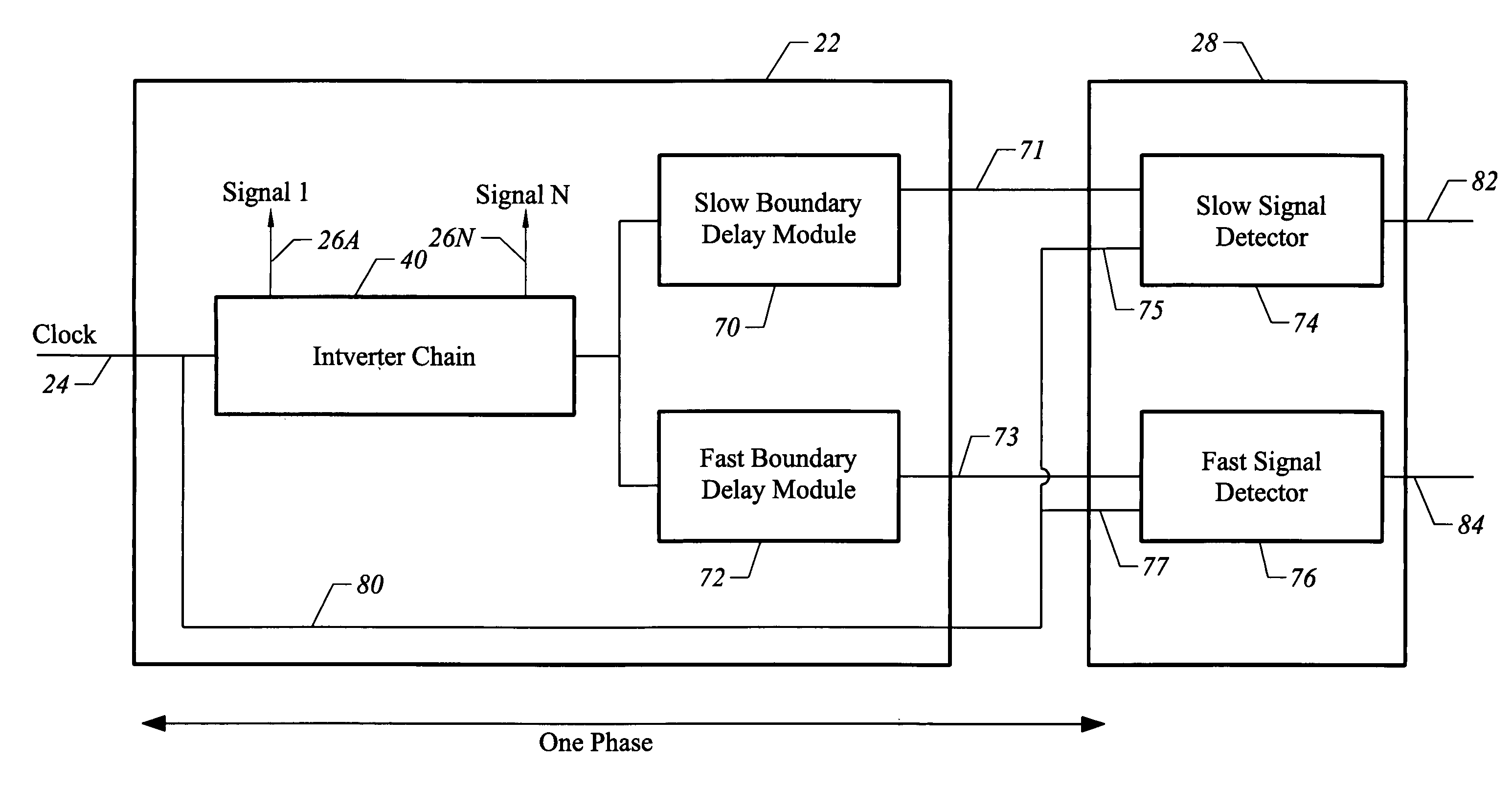
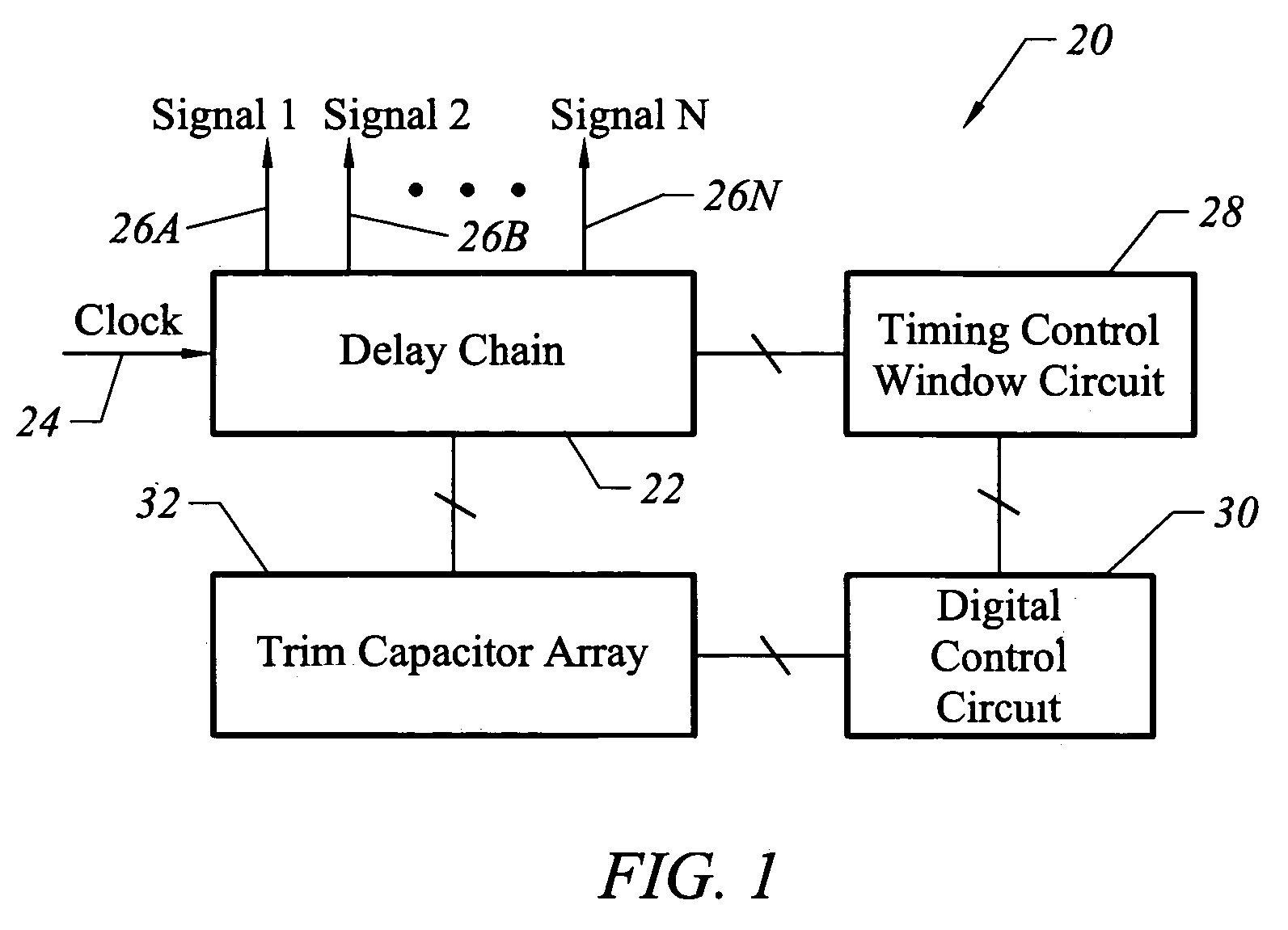
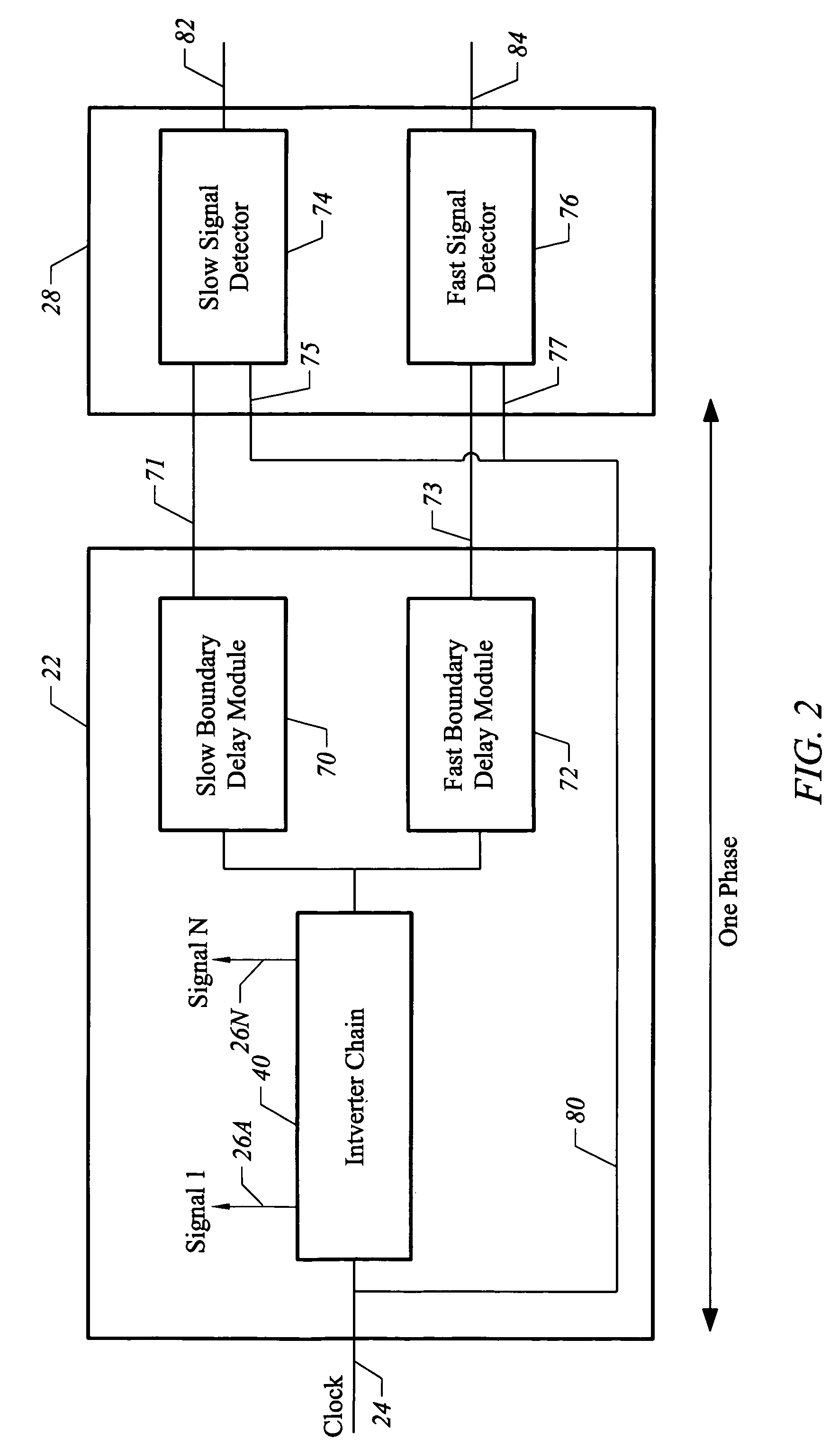
[0024]FIG. 1 illustrates an apparatus 20 for generating multi-phase signals through the digital control of trim capacitors. The apparatus 20 includes a delay chain 22, which receives a clock signal on an input node 24. The delay chain produces multi-phase signals on tap lines 26A–26N. The output of the delay chain includes a slow boundary signal and a fast boundary signal, which are applied to a timing control window circuit 28. The timing control window circuit 28 compares a reference signal to a timing window framed by the slow boundary signal and the fast boundary signal. If the reference signal is outside this timing window, then a control signal is applied to a digital control circuit 30. The digital control circuit 30 produces a digital capacitive trim signal, which is applied to a trim capacitor array 32. The digital capacitive trim signal controls the capacitive loading on the delay chain, and thereby controls the multi-phase signals produced by the delay chain 22.

[0025]Thus...


PUM


Abstract

An apparatus for generating multi-phase signals includes a delay chain to produce multi-phase signals, a slow boundary signal, and a fast boundary signal. An array of trim capacitors is connected to the delay chain. A timing control window circuit produces a control signal when a reference signal is outside a timing control window defined by the slow boundary signal and the fast boundary signal. A digital circuit produces a digital capacitive trim signal for application to the array of trim capacitors in response to the control signal. The digital capacitive trim signal alters the capacitive loading of the delay chain.

Description

BRIEF DESCRIPTION OF THE INVENTION[0001]This invention relates generally to delay-locked loops and related techniques for forming multi-phase signals. More particularly, the invention relates to a technique for generating multi-phase signals through the digital control of trim capacitors.BACKGROUND OF THE INVENTION[0002]Modern high-performance digital chips, such as microprocessors, often employ a single-phase clock for sequencing of internal events. Such clocks provide for two timing edges per cycle: the clock rising edge and the clock falling edge. Large on-chip memories, such as caches, often need more sequence control-timing edges than are provided by a single-phase system clock.[0003]Prior art efforts to generate more timing edges than the system clock provides revolve around circuit and device-characteristic dependent delay chains, so-called “self-timed” circuits. These delay chains typically comprise a set of serially connected inverters, with individual tap lines connected b...

Claims


Application Information

Patent Timeline
Patent Type & Authority Patents(United States)
IPC IPC(8): H03L7/06
CPCH03L7/087H03L7/0814
Inventor REAVES, JIMMY LEE
Owner ARM FINANCE OVERSEAS LTD
Learn More