Electromagnetic actuator

a technology of actuators and actuators, applied in the direction of magnets, operating means/releasing devices of valves, magnetic bodies, etc., can solve the problems of reducing the wear of both sliding faces, and achieve the effects of optimizing the surface roughness level, prolonging the life of use, and improving productivity

Inactive Publication Date: 2006-01-17
DENSO CORP
View PDF12 Cites 8 Cited by
  • Summary
  • Abstract
  • Description
  • Claims
  • Application Information

AI Technical Summary

Benefits of technology

[0010]The present invention has been made with reference to such investigation, and an object of the present invention is to provide an electromagnetic actuat

Problems solved by technology

Eventually, the wear of bo

Method used


Image

  • Electromagnetic actuator
  • Electromagnetic actuator
  • Electromagnetic actuator

Examples


Embodiment Construction

[0021]The following description of the preferred embodiment(s) is merely exemplary in nature and is in no way intended to limit the invention, its application, or uses.

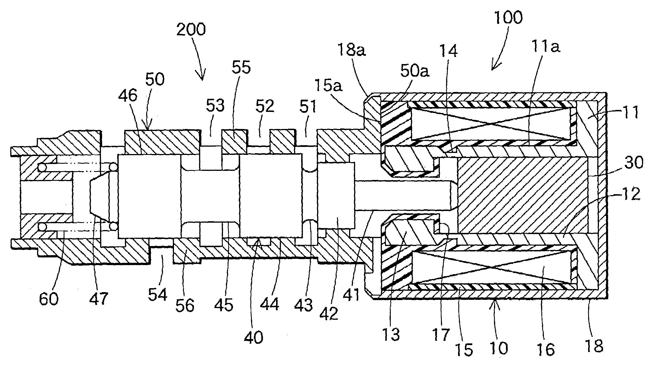
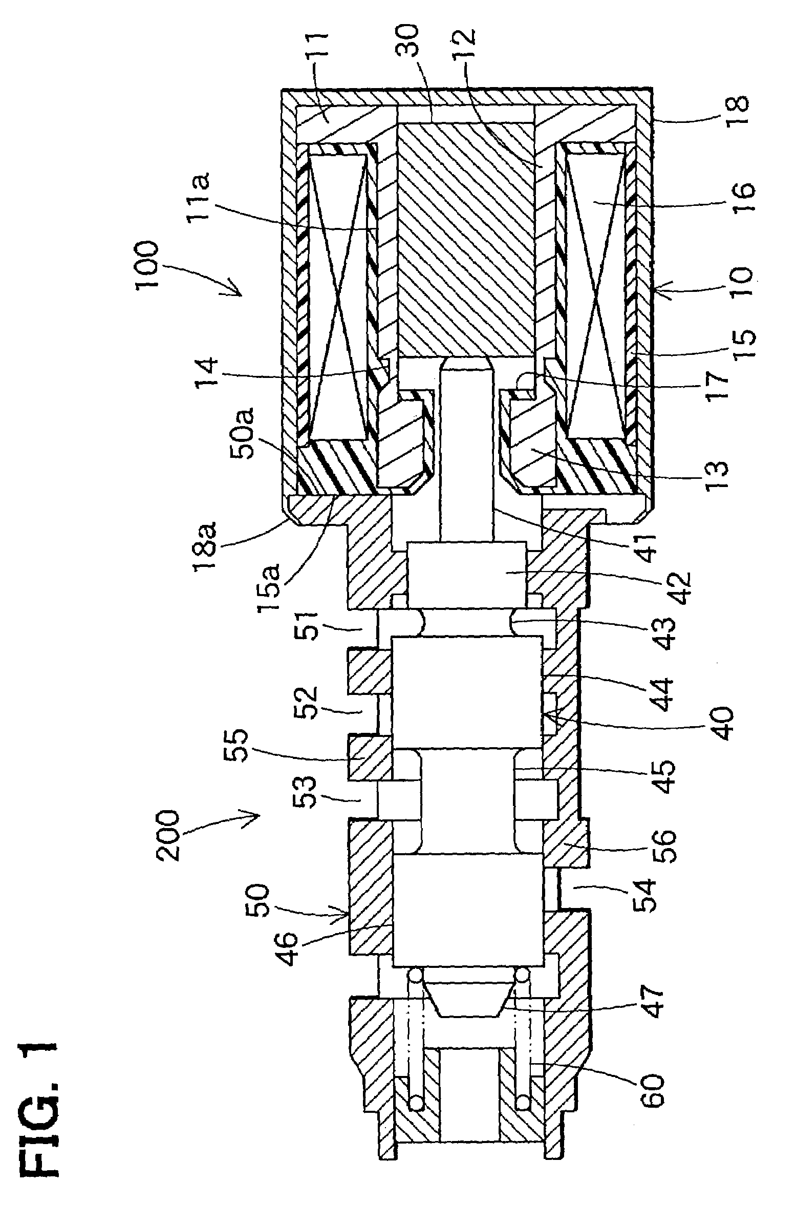
[0022]Now the preferred embodiments of the invention will be described with reference to the accompanying drawings. FIG. 1 is a cross-sectional view of a flow control device equipped with an electromagnetic actuator according to an embodiment of the invention. This flow control device is, for example, a spool type hydraulic pressure control valve that controls the hydraulic pressure of operation oil supplied to the hydraulic pressure control device of an automatic transmission of a vehicle or the like.

[0023]Referring now to FIG. 1, the flow control device includes an electromagnetic actuator 100 and a valve unit 200.

(1) Electromagnetic Actuator 100

[0024]The electromagnetic actuator 100 constitutes a linear solenoid, equipped with a stator 10 and a cylindrical movable core (plunger) 30.

[0025]The stator 10 has a hollow ...


PUM


Abstract

An electromagnetic actuator has a movable core, a housing that holds the movable core so that the core may freely reciprocate, and an attractive part that applies a magnetic force to pull the movable core in one of the reciprocating directions. The electromagnetic actuator further has a stator that constitutes a magnetic circuit along with the movable core. At least one of the sliding faces of the housing and the movable core in contact with each other is subjected to gas soft nitriding, salt-bath soft nitriding, sulfo-nitriding, or nitriding treatment. The surface roughness of such a nitrided face is controlled to be within a prescribed range, so that the wear of the sliding faces of the movable core and the housing can be reduced.

Description

CROSS REFERENCE TO RELATED APPLICATIONS[0001]This application is based upon, claims the benefit of priority of, and incorporates by reference the contents of prior Japanese Patent Application No. 2002-96839 filed Mar. 29, 2002 and No. 2002-370696 filed Dec. 20, 2002.BACKGROUND OF THE INVENTION[0002]1. Field of the Invention[0003]The present invention relates to electromagnetic actuators, and more specifically, to an electromagnetic actuator of which a housing of the movable core constitutes part of the magnetic circuit.[0004]2. Description of the Related Art[0005]As disclosed in Japanese Patent Laid-Open Publication No. 2001-332419, a known conventional electromagnetic actuator is equipped with a housing for holding a movable core so that it may freely reciprocate back and forth and a stator having an attraction part that exerts a magnetic attractive force on the movable core in either of the reciprocating directions. The stator is configured together with the movable core to form a...

Claims


Application Information

Patent Timeline
IPC IPC(8): H01F7/08F16K31/06H01F7/16
CPCH01F7/1607
Inventor MATSUSAKA, NOBORUNAKANE, HIROYUKIIWASE, ATSUSHI
Owner DENSO CORP
Why Eureka
Try Eureka