Adjusting track density over disk radius by changing slope of spiral tracks used to servo write a disk drive

a technology of spiral track and disk drive, which is applied in the direction of maintaining head carrier alignment, digital recording, instruments, etc., can solve the problems of not disclosing the way to adjust the track density, the external servo writer is expensive and requires a clean room environment, and the internal servo writer is an expensive bottleneck in the disk drive manufacturing process

Inactive Publication Date: 2006-01-17
WESTERN DIGITAL TECH INC
View PDF15 Cites 169 Cited by
  • Summary
  • Abstract
  • Description
  • Claims
  • Application Information

AI Technical Summary

Benefits of technology

[0012]In still another embodiment, the step of demodulating the high frequency signal in the spiral tracks comprises the step of opening a demodulation window using the servo write clock, further comprising the step of shifting the demodulation window in time relative to the servo write clock to seek the head from the first target circular path to a second target circular path.
[0013]In yet another embodiment, the step of demodulating the high frequency signal in the spiral tracks comprises the step of demodulating the high frequency signal into a plurality of servo burst signals. In one embodiment, the step of generating the position error signal comprises the step of computing a difference between the servo burst signals. In another embodiment, the step of shifting the demodulation window causes the plurality of servo burst signals to shift a corresponding amount to generate a non-zero position error signal.
[0014]In yet another embodiment, the step of demodulating the high frequency signal in the spiral tracks comprises the step of integrating the read signal to generate a ramp signal. In one embodiment, the position error signal is generated relative to a target sync mark in a spiral track and a reference point of the ramp signal. In another embodiment, the step of shifting the demodulation window causes a corresponding shift in the target sync mark to generate a non-zero position error signal.
[0015]In still another embodiment, the step of demodulating the high frequency signal in the spiral tracks comprises the step of generating an envelope signal from the read signal. In one embodiment, the position error signal

Problems solved by technology

However, external servo writers are expensive and require a clean room environment so that a head positioning pin can be inserted into the head disk assembly (HDA) without contaminating the disk.
Thus, external servo writers

Method used


Image

  • Adjusting track density over disk radius by changing slope of spiral tracks used to servo write a disk drive
  • Adjusting track density over disk radius by changing slope of spiral tracks used to servo write a disk drive
  • Adjusting track density over disk radius by changing slope of spiral tracks used to servo write a disk drive

Examples


Embodiment Construction

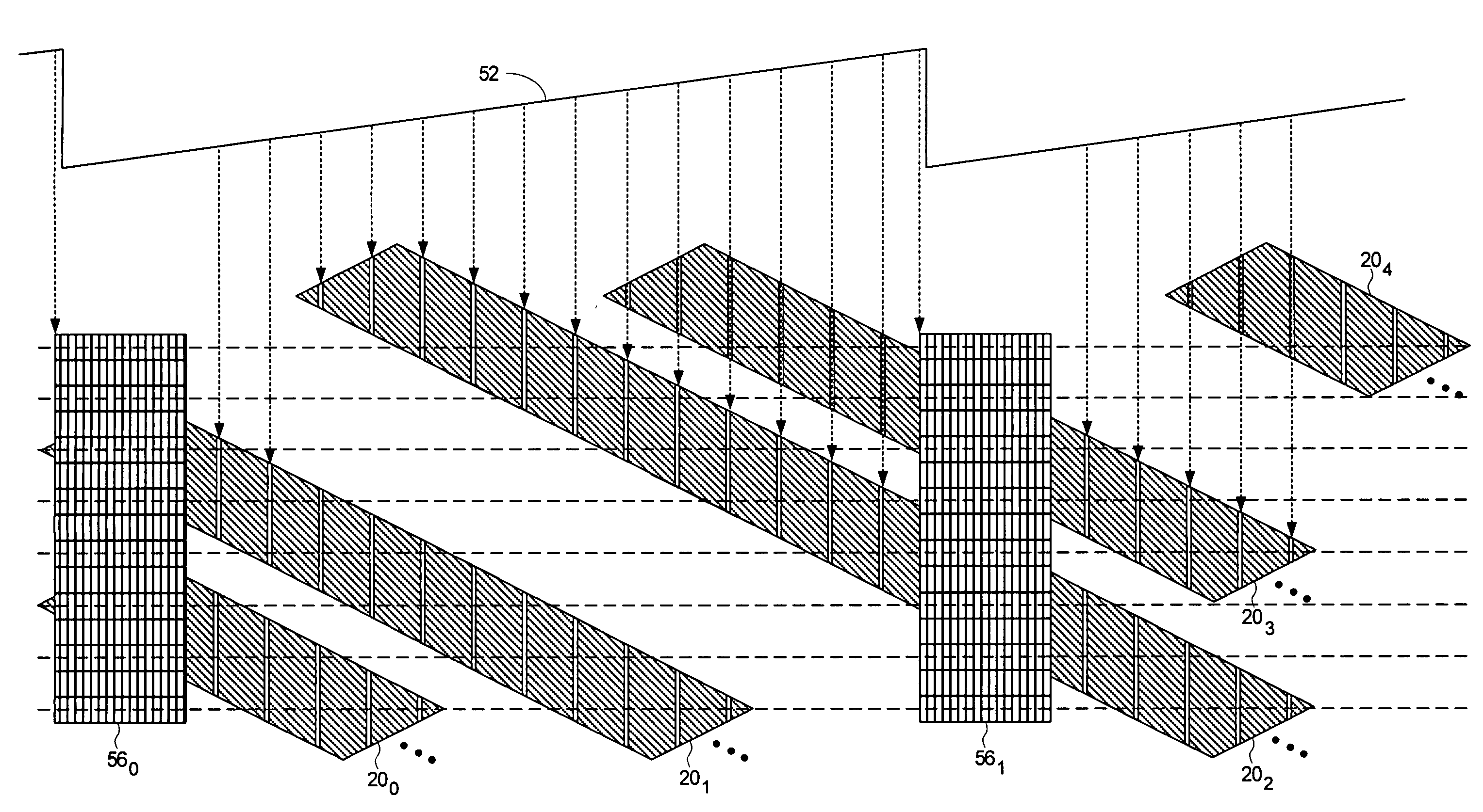
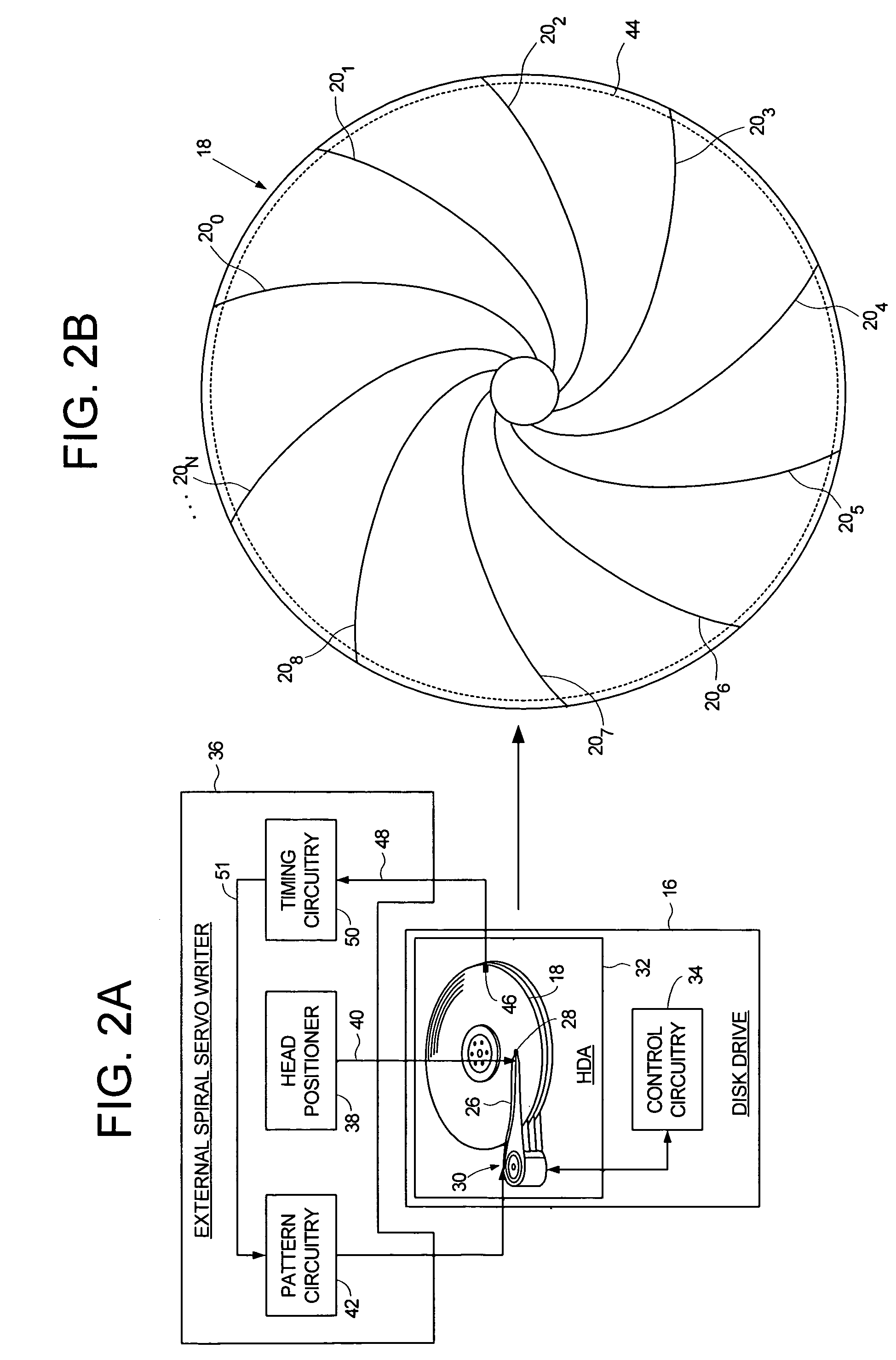
[0038]FIGS. 2A and 2B show an embodiment of the present invention wherein a plurality of spiral tracks 200–20N are written to a disk 18 of a disk drive 16 using an external spiral servo writer 36 (in an alternative embodiment, the spiral tracks are stamped onto the disk using magnetic printing techniques). The disk drive 16 comprises control circuitry 34 and a head disk assembly (HDA) 32 comprising the disk 18, an actuator arm 26, a head 28 coupled to a distal end of the actuator arm 26, and a voice coil motor 30 for rotating the actuator arm 26 about a pivot to position the head 28 radially over the disk 18. A write clock is synchronized to the rotation of the disk 18, and the plurality of spiral tracks 200–20N are written on the disk 18 at a predetermined circular location determined from the write clock. Each spiral track 20i comprises a high frequency signal 22 (FIG. 4B) interrupted at a predetermined interval by a sync mark 24.

[0039]The spiral tracks 200–20N are written (or sta...


PUM


Abstract

A method and apparatus is disclosed for adjusting the track density over the disk radius by changing the slope of spiral tracks used to servo write a disk drive. A plurality of spiral tracks are written to the disk wherein each spiral track comprises a high frequency signal interrupted at a predetermined interval by a sync mark. A slope of the spiral tracks over a first radial segment of the disk is substantially steeper than the slope of the spiral tracks over a second radial segment of the disk. The head internal to the disk drive is used to read the spiral tracks in order to write product servo sectors to the disk to define a plurality of data tracks. The steeper slope of the spiral tracks over the first radial segment causes a track density of the data tracks to be lower over the first radial segment compared to the track density of the data tracks over the second radial segment.

Description

BACKGROUND OF THE INVENTION[0001]1. Field of the Invention[0002]The present invention relates to disk drives for computer systems. More particularly, the present invention relates to adjusting track density over disk radius by changing slope of spiral tracks used to servo write a disk drive.[0003]2. Description of the Prior Art[0004]When manufacturing a disk drive, servo sectors 20–2N are written to a disk 4 which define a plurality of radially-spaced, concentric data tracks 6 as shown in the prior art disk format of FIG. 1. Each data track 6 is partitioned into a plurality of data sectors wherein the servo sectors 20–2N are considered “embedded” in the data sectors. Each servo sector (e.g., servo sector 24) comprises a preamble 8 for synchronizing gain control and timing recovery, a sync mark 10 for synchronizing to a data field 12 comprising coarse head positioning information such as a track number, and servo bursts 14 which provide fine head positioning information. The coarse h...

Claims


Application Information

Patent Timeline
IPC IPC(8): G11B21/02G11B5/09G11B5/596
CPCG11B5/59633
Inventor CHUE, JACK M.WEERASOORIYA, SIRI S.LEE, TEHRI S.
Owner WESTERN DIGITAL TECH INC
Why Eureka
Try Eureka