Method and device for monitoring a mass flow in a pneumatic pipeline

a technology of mass flow and pipeline, which is applied in the direction of measurement devices, volume/mass flow measurement, instruments, etc., can solve the problem that the acoustic waves that are sensed on the impact body cannot be falsified through the acoustic noise of the structur

Inactive Publication Date: 2006-01-24
PAUL WURTH SA
View PDF13 Cites 29 Cited by
  • Summary
  • Abstract
  • Description
  • Claims
  • Application Information

AI Technical Summary

Benefits of technology

[0014]The stemlike impact body can be easily isolated from the pneumatic pipeline with regard to structure-born acoustic noise. Thus, the structure-born acoustic waves that are sensed on the impact body cannot be falsified through structure-born acoustic noise in the pipeline.
[0017]A preferred device for monitoring the mass flow a particulate solids flow in a pneumatic pipeline comprises a measuring chamber with an inlet connection, an impact body located within the measuring chamber and an acoustic transducer associated with the impact body. The inlet connection is designed to blow the particulate solids flow as a compact solid / gas jet onto the impact body, so that the compact solid / gas jet impacts onto the impact body with substantially its whole cross-section. In accordance with an important aspect of the present invention, the impact body is a stemlike body axially penetrating into the measuring chamber in axial prolongation of the central axis of the inlet connection, so that the compact solid / gas jet impacts onto a frontal impact surface of the stemlike impact body with substantially its whole cross-section, and an acoustic transducer is associated with the impact body outside of the measuring chamber for sensing structure-born acoustic waves generated by the compact solid / gas jet impacting onto the impact body and for converting the sensed signals in an output signal. It will be particularly appreciated that the present device allows to reliably monitor particulate solids flow in a pneumatic pipeline under very adverse conditions, such as e.g.: high temperatures, very dense and / or inhomogeneous flow regimes and / or very abrasive particulate solids.

Problems solved by technology

In contrast to known passive acoustic methods, the method does not sense structure-born acoustic waves directly produced by the particulate solids flow.
Thus, the structure-born acoustic waves that are sensed on the impact body cannot be falsified through structure-born acoustic noise in the pipeline.

Method used


Image

  • Method and device for monitoring a mass flow in a pneumatic pipeline
  • Method and device for monitoring a mass flow in a pneumatic pipeline

Examples


Embodiment Construction

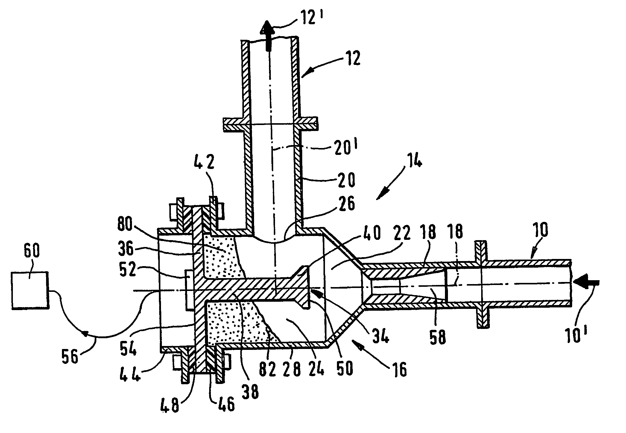
[0023]In FIG. 1, reference number 10 identifies an upstream section and reference number 12 a downstream section of a pneumatic pipeline. Such a pneumatic pipeline is used to convey particulate materials, as e.g. pulverized or granular materials, using a gaseous fluid, usually air or an inert gas, as carrier medium. Such a particulate solids flow is schematically identified by arrow 10′, respectively 12′.

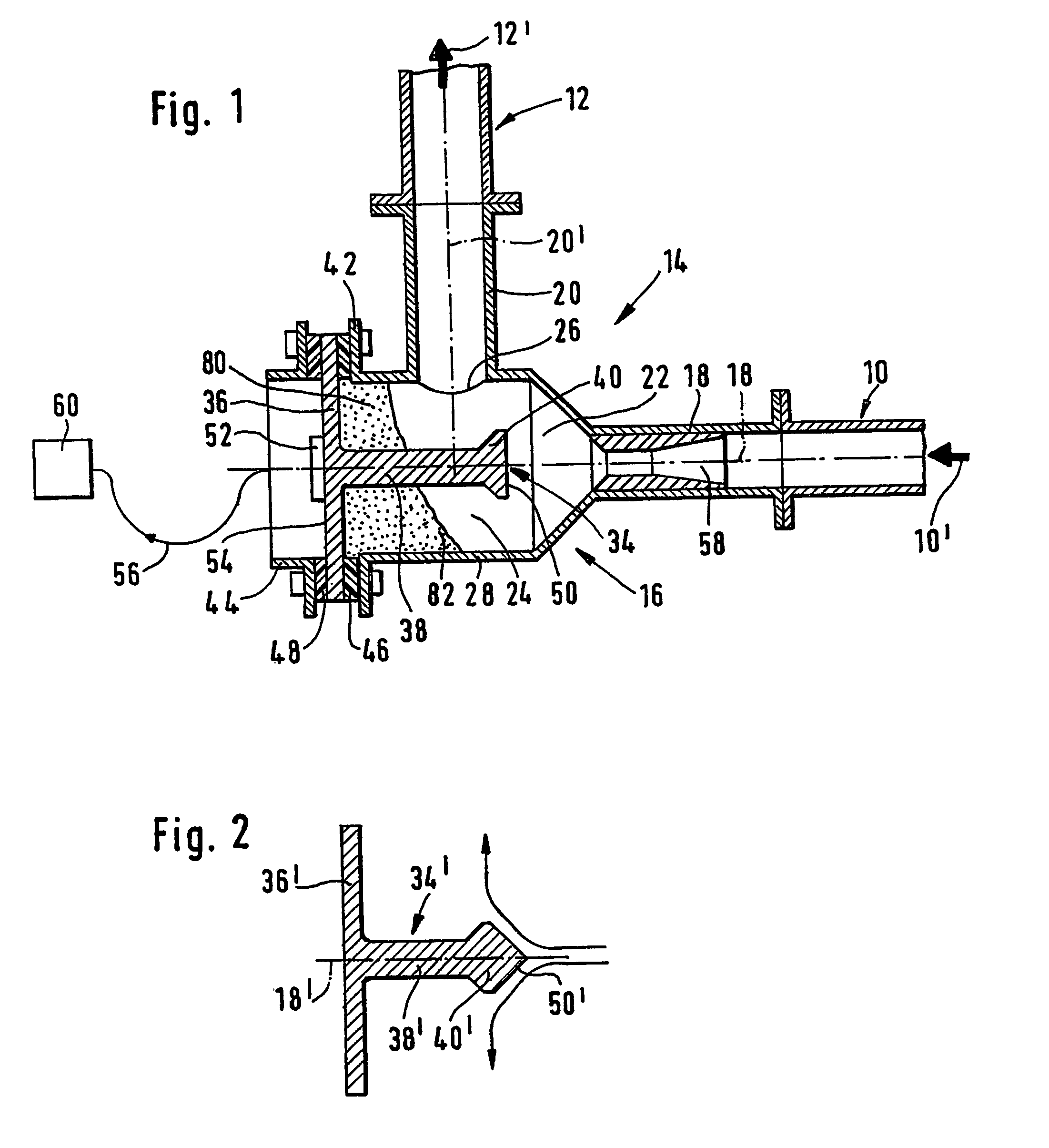
[0024]Reference number 14 globally identifies a device for monitoring the mass low a particulate solids flow in the pneumatic pipeline 10′, 12′. This device 14 is connected between the upstream section 10 and the downstream section 12 of the pneumatic pipeline in replacement of a pipeline bend. It comprises a measuring chamber 16 with an inlet connection 18 and an outlet connection 20. The central axes 18′ and 20′ of the inlet connection 18 and the outlet connection 20 are perpendicular to each other. The upstream section 10 of the pneumatic pipeline is axially connected to the inle...


PUM


Abstract

A device for monitoring the mass flow of a particulate solids flow in a pneumatic pipeline includes a measuring chamber and an impact body. Through an inlet connection the particulate solids flow is blown as a compact solid / gas jet onto the impact body, so as to impact thereon with substantially its whole cross-section. An acoustic transducer is associated with the impact body for sensing structure-born acoustic waves, which are generated by the compact solid / gas jet impacting onto the impact body, and transforming them into an output signal. Signal processing process the output signal so as to derive a value that is representative of the mass flow rate of the particulate solids flow.

Description

CROSS-REFERENCE TO RELATED APPLICATIONS[0001]This application is entitled to the benefit of and incorporates by reference in their entireties essential subject matter disclosed in International Application No. PCT / EP03 / 00661 filed on Jan. 23, 2003, and Luxembourg Patent Application No. 90 883 filed on Jan. 23, 2002.FIELD OF THE INVENTION[0002]The present invention relates to a method and device for monitoring a mass flow in a pneumatic pipeline.BACKGROUND OF THE INVENTION[0003]Pneumatic pipelines convey particulate solids, as e.g. pulverized or granular materials, using a gaseous fluid, usually air or an inert gas, as carrier medium. As pneumatic pipelines are becoming widespread in many areas of industry, there is an urgent need for simple and reliable methods and devices for monitoring a flow of particulate solids in a pneumatic pipeline and, more particularly, for monitoring the mass flow rate thereof. Being capable of continuously monitoring the mass flow rate in pneumatic pipel...

Claims


Application Information

Patent Timeline
Patent Type & Authority Patents(United States)
IPC IPC(8): B65G51/36G01F1/00G01F1/66G01F1/74
CPCG01F1/74G01F1/666G01F1/66
Inventor KROEMMER, YVANBREDEN, EMILE
Owner PAUL WURTH SA
Why Eureka
Try Eureka