
Microchannel apparatus, methods of making microchannel apparatus, and processes of conducting unit operations

a microchannel apparatus and microchannel technology, applied in the direction of manufacturing tools, lighting and heating apparatus, laminated elements, etc., can solve the problems of new difficulties of devices and require novel construction methods, and achieve the effects of less waste, superior flow characteristics, and reduced costs

Inactive Publication Date: 2006-01-24
VELOCYS CORPORATION
View PDF39 Cites 95 Cited by
  • Summary
  • Abstract
  • Description
  • Claims
  • Application Information

AI Technical Summary

Benefits of technology

[0010]In another aspect, the invention provides a method of making a laminated device, comprising: placing a metal can around a stack of laminae; pressing the can against the stack of laminae; and reducing the pressure to result in an article comprising metal sheeting bonded onto the sides of the stack of laminae.
[0025]Any of the articles described herein may have multiple layers and repeating sets of layers (repeating units). For example, 2, 10, 50 or more repeating units within a laminate. This multiplicity, or “numbering up” of layers creates added capacity of microchannel laminated devices.
[0026]Various embodiments of the present invention may possess advantages such as: lower costs, less waste, superior flow characteristics, and the ability to stack components to make very small features in relatively large devices (for example, 0.1 mm wide ribs with 0.1 mm inter-rib spaces extending for 30 cm or more). In some preferred embodiments, methods of the invention can be characterized by their efficient use of materials, for example producing articles with internal microchannels, where casting is not used, and essentially no material is wasted—this may be contrasted to stamping or ablative methods in which material is removed in the process of forming the device.GLOSSARY

Problems solved by technology

Although these devices offer many advantages, making such devices presents new difficulties and requires novel methods of construction.

Method used


Image

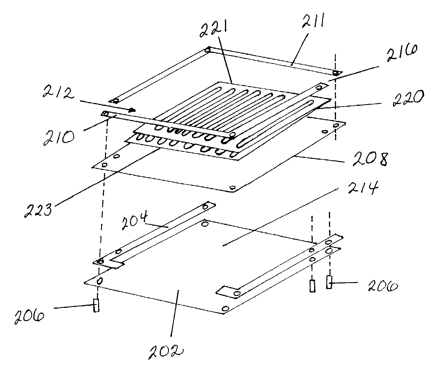
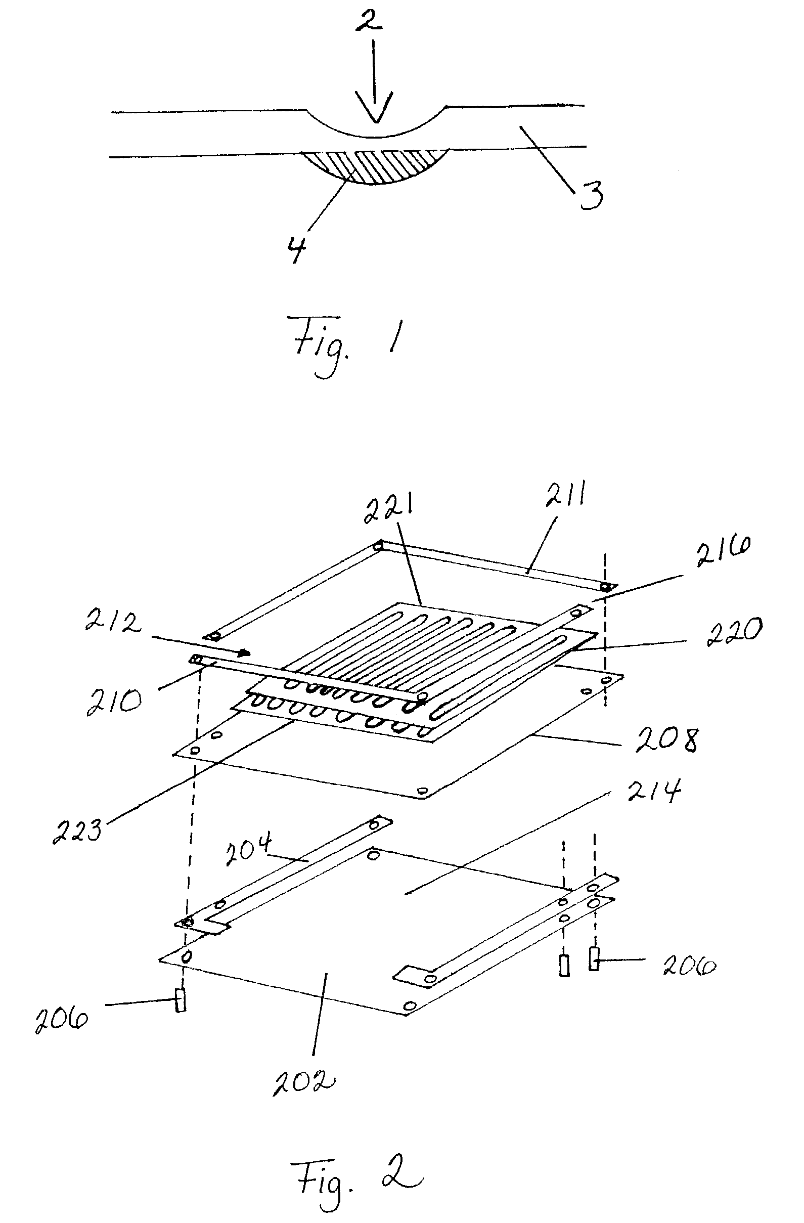
  • Microchannel apparatus, methods of making microchannel apparatus, and processes of conducting unit operations
  • Microchannel apparatus, methods of making microchannel apparatus, and processes of conducting unit operations
  • Microchannel apparatus, methods of making microchannel apparatus, and processes of conducting unit operations

Examples


examples

[0096]A test device was constructed from the following pieces (described with thickness in the stacking direction, and reference numerals corresponding to FIG. 17):[0097]52. ribs 0.06 inch wide×0.1 inch thick×3.685 inch long;[0098]54. ribs 0.06 inch wide×0.2 inch thick×3.130 inch long;

[0099]Ribs 0.06 inch wide×0.200 inch thick×2.14 inch long (second type of rib)[0100]56. thin sheets 3.140 inch wide×0.020(??) inch thick×3.690 inch long;[0101]58. base plates 3.140 inch wide×0.5 inch thick×3.690 inch long;[0102]60. edge strips 0.500 inch wide×0.2 inch thick×3.140 inch long;[0103]62. edge strips 0.500 inch wide×0.1 inch thick×3.690 inch long; and[0104]64. braze foil is placed above and below each edge strip.

[0105]During construction, the ribs are aligned on a thin sheet using the comb-like fixture described above and edge strips were also placed on the thin sheet. The ribs and edge strips were tack welded in place. Preferably the welding step uses resistance welding or laser (spot) weld...


PUM

PropertyMeasurementUnit
lengthaaaaaaaaaa
aspect ratioaaaaaaaaaa
lengthaaaaaaaaaa

Abstract

Novel methods of making laminated, microchannel devices are described. Examples include: assembly from thin strips rather than sheets; and hot isostatic pressing (HIPing) to form devices with a hermetically sealed wall. Laminated microchannel articles having novel features are also described. The invention includes processes conducted using any of the articles described.

Description

INTRODUCTION[0001]In recent years there has been intense industrial and academic interest toward developing microscale devices for chemical processing. A recent review of microscale reactors, containing 236 citations, has been provided by Gavrilidis et al., “Technology And Applications Of Microengineered Reactors,” Trans. IChemE, Vol. 80, Part A, pp. 3–30 (January 2002). Microscale chemical processors, which are characterized by fluid channel dimensions of about 5 mm or less, can provide unique advantages due to short heat and mass transfer distances, and, in some instances, different flow characteristics. Although these devices offer many advantages, making such devices presents new difficulties and requires novel methods of construction.[0002]The recent patent literature describes multiple types of microscale devices and / or methods of manufacture. For example, Wegeng et al., in WO 01 / 95237 A2, described novel types of integrated reactors that are made by laminated sheets of numero...

Claims


Application Information

Patent Timeline
Patent Type & Authority Patents(United States)
IPC IPC(8): B01J10/00F28F3/08B01F5/06B01F13/00B01J19/00B23K20/02B23K31/02F28D9/00F28F3/04F28F13/06
CPCB01F5/061B01F13/0059B01J19/0093B23K20/023B23K31/02F28D9/0062F28F3/048F28F13/06B01J2219/00783B01J2219/00835F28F2260/02B01J2219/00873F28F2275/143B01F33/30B01F25/431951B01F25/43172B01F25/43197
Inventor TONKOVICH, ANNA LEEROBERTS, GARYFITZGERALD, SEAN P.WERNER, TIMOTHY M.SCHMIDT, MATTHEW B.LUZENSKI, ROBERT J.CHADWELL, G. BRADLEYMATHIAS, JAMES A.GUPTA, ABHISHEKKUHLMANN, DAVID J.YUSCHAK, THOMAS D.
Owner VELOCYS CORPORATION
Learn More