System and method for controlling temperature control elements that are used to alter liquid temperature

a technology of temperature control elements and control elements, applied in the direction of control system, testing/monitoring, immersion heating arrangements, etc., can solve the problems of frequent and/or long activation of heating elements, water tank typically does not provide total thermal insulation, and heat from the water often dissipates through

Inactive Publication Date: 2006-01-24
A O SMITH
View PDF24 Cites 44 Cited by
  • Summary
  • Abstract
  • Description
  • Claims
  • Application Information

AI Technical Summary

Problems solved by technology

The water tank typically does not provide total thermal insulation, and heat from the water often dissipates through the tank and into the surrounding environment.
Furthermore, as water is drawn from the tank and used, unheated water from the water source is drawn into the tank to replenish the tank's water supply.
Moreover, activation of the heating element can be particularly frequent and / or long during times of high water usage and for water tanks providing poor thermal insulation.
As a result, the operational costs associated with a water heater are directly related to the amount of heat generated by the heating element.
More specifically, any increase in the amount of heat generated by the heating element normally increases the energy costs and, therefore, the overall operational costs associated with the water heater.
Another problem with conventional water tanks pertains to failure of the heating element.
Over time, the frequent transitions of the heating element increase the wear experienced by the heating element, and the heating element eventually fails.
However, during the time that it takes to fix or replace the water tank, the water tank often fails to maintain the water temperature at the desired level.
In most situations, a user has no alternative source for heated water and, therefore, is not able to keep water at the desired temperature until the water tank is either fixed or replaced.
This can be very inconvenient for the user, and the longer that it takes to fix or replace the water tank, the more the user is inconvenienced.
Thus, the operational costs associated with a water cooler are directly related to the amount of cooling performed by the cooling element.
More specifically, any increase in the amount of cooling performed by the cooling element normally increases the energy costs and, therefore, the overall operational costs associated with the water cooler.

Method used


Image

  • System and method for controlling temperature control elements that are used to alter liquid temperature
  • System and method for controlling temperature control elements that are used to alter liquid temperature
  • System and method for controlling temperature control elements that are used to alter liquid temperature

Examples


Embodiment Construction

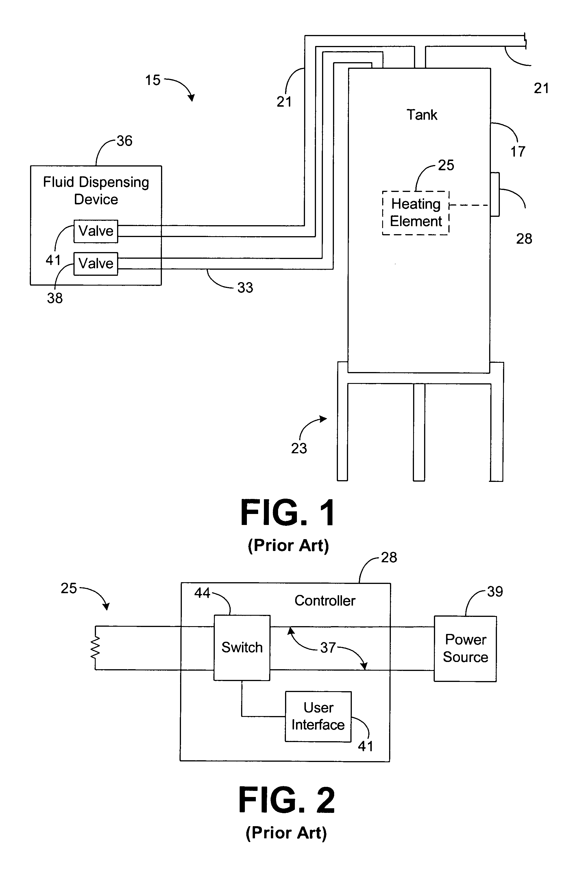
[0051]FIG. 1 depicts a conventional water heating system 15. The system 15 includes a water tank 17 that receives and stores water from a water pipe 21. If desired, the tank 17 may reside on a base or stand 23 that supports the tank 17, as shown by FIG. 1. A temperature control element, referred to as a “heating element 25,” within the tank 17 heats, under the direction and control of a controller 28, the water within the tank 17 to a desired temperature. The heated water within the tank 17 may be drawn through a pipe 33 to one or more dispensing devices 36, such as a faucet, nozzle, or shower head, for example, which dispenses the heated water for use by a user. The dispensing device 36 normally includes a valve 38 for controlling water flow and, more particularly, for controlling whether or not the device 36 dispenses water from the pipe 33. When the valve 38 is opened, water flows out of the dispensing device 36 and water from the tank 17 flows out of the tank 17 and into the pip...


PUM

PropertyMeasurementUnit
timeaaaaaaaaaa
temperatureaaaaaaaaaa

Abstract

A system for controlling temperature control elements used to alter temperatures of a liquid comprises a temperature sensor, a first temperature control element, a second temperature control element, and logic. The temperature sensor is configured to sense temperatures of the liquid, and the first and second temperature control elements are each configured to alter a temperature of the liquid. The logic is configured to selectively control, based on the sensed temperatures, activation states of the first and second temperature control elements such that a total activation time associated with the first temperature control element is substantially equal to a total activation time associated with the second temperature control element.

Description

CROSS-REFERENCE TO RELATED APPLICATION[0001]This document is a continuation of U.S. patent application Ser. No. 10 / 300,310 entitled “System and Method for Controlling Temperature Control Elements that are Used to Alter Liquid Temperature,” and filed on Nov. 20, 2002 now abandoned, which is incorporated herein by reference. U.S. patent application Ser. No. 10 / 300,310 claims priority to and the benefit of the filing date of U.S. Provisional Application No. 60 / 417,926, entitled “System and Method for Controlling Water Temperature within a Water Tank,” and filed on Oct. 11, 2002, which is incorporated herein by reference.BACKGROUND OF THE INVENTION[0002]1. Field of the Invention[0003]The present invention generally relates to liquid heating and cooling techniques and, in particular, to a system and method for controlling temperature control elements used to alter temperatures of liquids residing within tanks.[0004]2. Related Art[0005]Water tanks are often employed to provide users with ...

Claims


Application Information

Patent Timeline
Patent Type & Authority Patents(United States)
IPC IPC(8): H05B1/02G01K7/42G05B23/02G05D23/19
CPCG01K7/42G05B23/0283G05D23/1951
Inventor PATTERSON, WADE C.PHILLIPS, TERRY G.
Owner A O SMITH
Why Eureka
Try Eureka