Compact inverse-telephoto infrared imaging optical system

a technology of infrared imaging and optical system, which is applied in the direction of optical elements, instruments, optical radiation measurement, etc., can solve the problems of large infrared sensor weight and size, large-diameter lens cost and large-diameter lens, etc., and achieves low weight and small size.

Inactive Publication Date: 2006-01-24
RAYTHEON CO
View PDF9 Cites 23 Cited by
  • Summary
  • Abstract
  • Description
  • Claims
  • Application Information

AI Technical Summary

Benefits of technology

[0009]The present invention provides a compact inverse-telephoto infrared imaging optical system having a wide field of view, fast optical speed, and small ratio of the physical length to the focal length. The ratio of the physical length to the focal length is typically on the order of 8:1 to 10:1, compared to 20:1 to 30:1 for prior inverse-telephoto infrared imaging optical systems. The present inverse-telephoto infrared imaging optical system is therefore much smaller and lighter than the prior inverse-telephoto infrared imaging optical systems. Additionally, the image quality and distortion in optical systems of the present approach are significantly better than available in prior approaches.
[0014]The embodiments of the present approach all have an external pupil between the rear lens group and the infrared detector. (An “external pupil” is a pupil that is not between the first and last lenses of the lens group of the optical system.) The external pupil allows the lenses to be used with a compact cold-shield positioned around the detector only but not around any of the lenses. The window of the cold shield is placed axially at a location near to that of the pupil. As noted, the present lens array is about ½ to ⅓ the length of prior inverse-telephoto infrared imaging optical systems, an important advantage where the application requires small size and low weight.

Problems solved by technology

For infrared optical systems, however, many fewer types of inverse-telephoto optical systems are available, because the infrared detector must be cryogenically cooled.
These very long lens systems result in a large weight and size for the infrared sensor, as well as require large-diameter lenses that are relatively expensive to manufacture.
It is difficult to package the long infrared sensor for many locations where it would otherwise be desirable to position the sensor, such as at the top of the tail of the aircraft.

Method used


Image

  • Compact inverse-telephoto infrared imaging optical system
  • Compact inverse-telephoto infrared imaging optical system
  • Compact inverse-telephoto infrared imaging optical system

Examples


Embodiment Construction

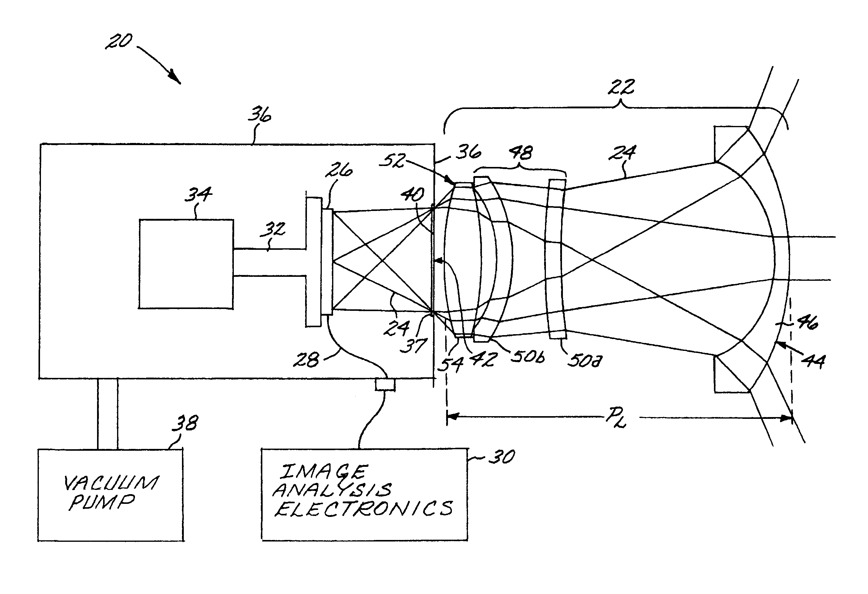
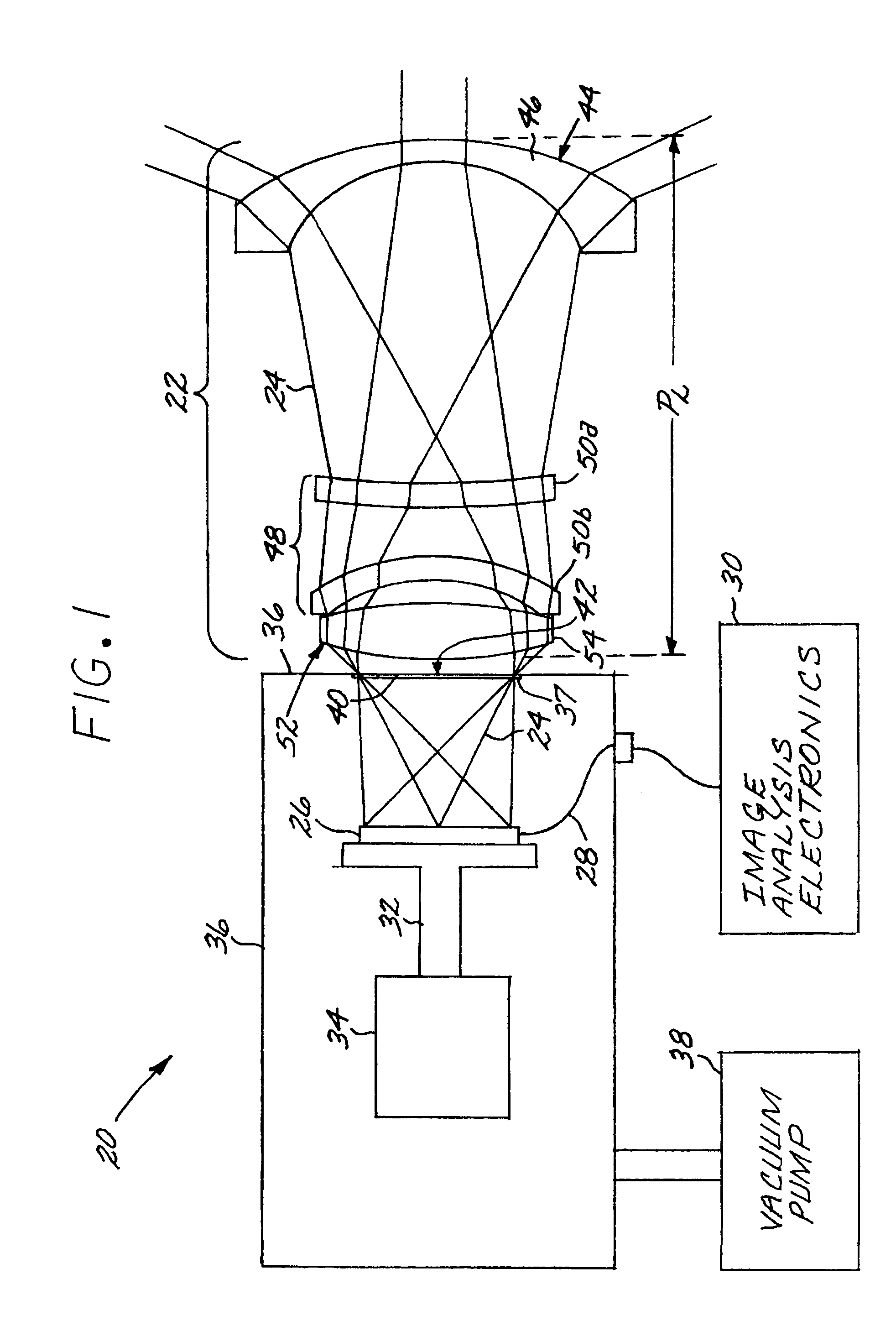
[0020]FIG. 1 depicts an infrared imaging optical system 20. The infrared imaging optical system 20 includes a lens group 22 that focuses an infrared light beam 24 from a scene onto an infrared detector 26. The infrared detector 26 is preferably a focal plane array (FPA) located at the focal plane of the lens group 22. The infrared detector 26 may be selected to be sensitive to any infrared wavelength or range of wavelengths. Preferably, it is sensitive to infrared wavelengths of from about 2 to about 7 micrometers wavelength, and more preferably the mid wavelength infrared range of from about 3 to about 5 micrometers wavelength. Infrared detectors 26 of these types and their manufacture are known in the art. The infrared detector 26 converts the incident infrared light beam 24 to an output signal 28, which is analyzed by image analysis electronics 30. Such image analysis electronics 30 is known in the art.

[0021]The preferred infrared detector 24 operates most effectively and efficie...


PUM


Abstract

An infrared imaging optical system includes a front lens group having negative optical power, wherein the front lens group comprises a front lens having a refractive index of from about 2.0 to about 3.0; an intermediate lens group that receives an infrared light beam from the front lens group, wherein the intermediate lens group comprises an intermediate lens having a refractive index of from about 1.35 to about 2.0; and a rear lens group having positive optical power, wherein the rear lens group receives the infrared light beam from the intermediate lens group, wherein the rear lens group comprises a rear lens having a refractive index of from about 2.0 to about 3.0, and wherein at least two of the front lens, the intermediate lens, and the rear lens have at least one aspheric surface thereon. The infrared imaging optical system further includes an infrared detector that receives the infrared light beam from the rear lens group. There is a pupil located between the rear lens group and the detector. There preferably is a cold shield around the detector having an opening therein at the pupil.

Description

[0001]This invention relates to an infrared imaging optical system and, more particularly, to an inverse-telephoto infrared optical system that is highly compact.BACKGROUND OF THE INVENTION[0002]Infrared imaging optical systems are typically used to view and image light energy in the infrared optical spectrum of from about 2 to about 7 micrometers wavelength, and more particularly from about 3 to about 5 micrometers wavelength. The production of infrared light is associated in many cases with the evolution of heat by hot objects such as engines or by the human body, and for that reason infrared light is widely used to detect such hot objects. Infrared energy is transmitted through many conditions which block visible light, such as clouds of particulate matter or water vapor.[0003]Missiles fired at an aircraft may be detected by the heat and corresponding infrared signatures produced by their engines, regardless of whether the missile is guided by an active or passive targeting syste...

Claims


Application Information

Patent Timeline
Patent Type & Authority Patents(United States)
IPC IPC(8): G01J5/02G02B13/04G02B13/06G02B13/14
CPCG02B13/14G02B13/06
Inventor COOK, LACY G.
Owner RAYTHEON CO
Why Eureka
Try Eureka