Exposure head and image forming apparatus using the same

a technology of image forming apparatus and exposure head, which is applied in the direction of visual presentation using printers, instruments, electrographic processes, etc., can solve the problems of inability to prevent uneven density with a high degree of accuracy, inability to highly accurate detection, poor light quantity, etc., and achieve the effect of improving the accuracy of detecting light quantity

Inactive Publication Date: 2006-01-24
SEIKO EPSON CORP
View PDF11 Cites 31 Cited by
  • Summary
  • Abstract
  • Description
  • Claims
  • Application Information

AI Technical Summary

Benefits of technology

[0005]The present invention has been made in consideration of these problems of the prior arts. Therefore, it is an object of the present invention to provide an exposure head, having light emitting parts such as organic EL light emitting elements which are aligned into an array configuration on a transparent substrate, in which light quanti...

Problems solved by technology

Therefore, since the detected quantity of light may be poor, highly accurate detection is impossible.
Accor...

Method used


Image

  • Exposure head and image forming apparatus using the same
  • Exposure head and image forming apparatus using the same
  • Exposure head and image forming apparatus using the same

Examples


first embodiment

[0117]As described above, according to the exposure head of the present invention and the image forming apparatus employing the same, a transparent substrate has plain faces substantially parallel to each other. One of the faces is a face on which the light emitting parts are formed and the other is a face from which light beams are projected. The transparent substrate is provided, at position(s) other than the face on which the light emitting parts are formed and than the face from which light beams are projected, with light quantity detecting means for detecting the quantity of light emitted from the light emitting parts. Therefore, it is possible to detect, at the position of the light quantity detecting means, light beams introduced by total internal reflection within the transparent substrate, thereby increasing the quantity of detected light and enabling the high-precision measurement of light quantity. As a result, even when there is a variation in light emitting characterist...

second embodiment

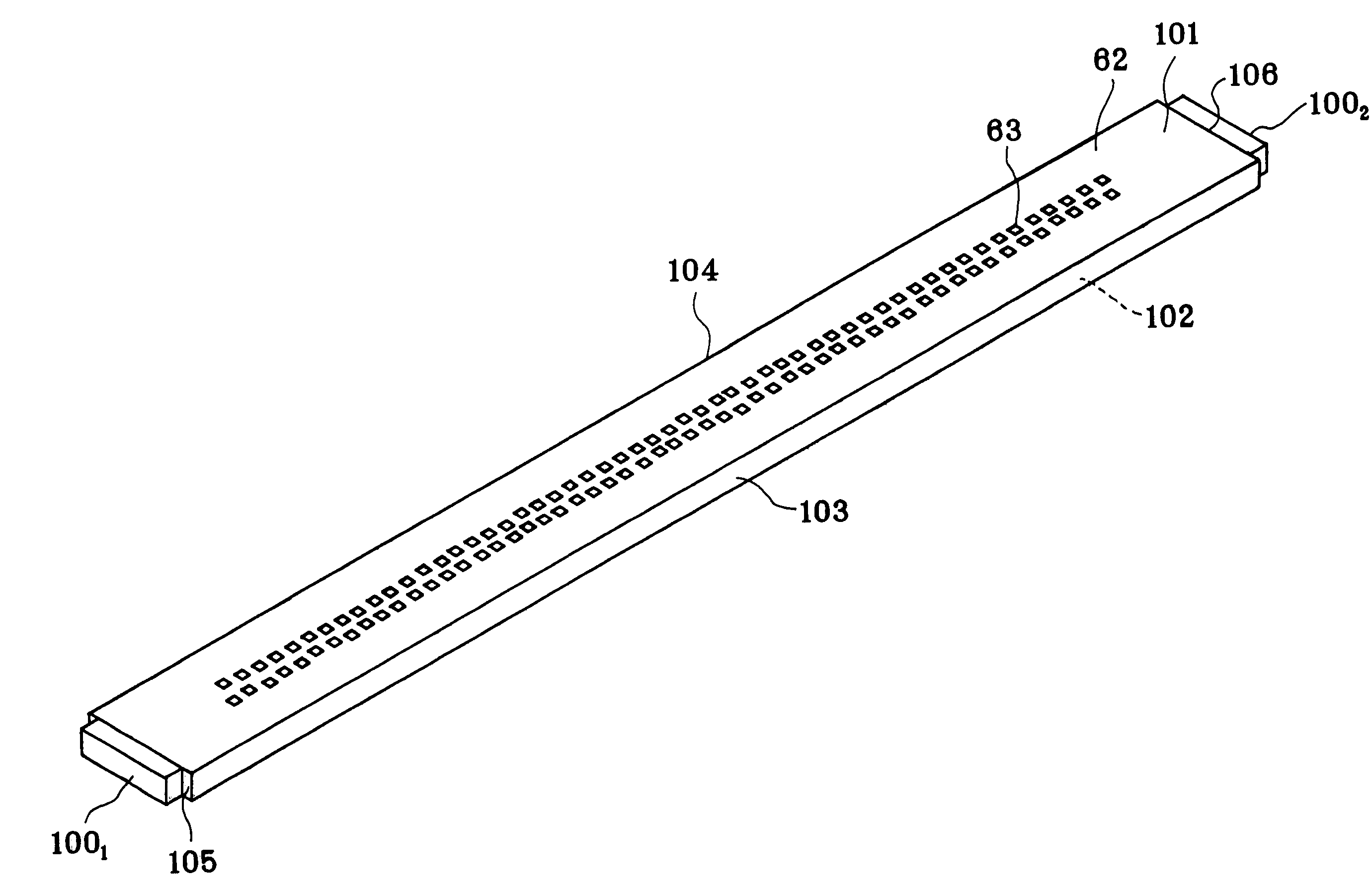
[0119]As for the exposure head of the second embodiment, a relation of the following equation is preferably satisfied:

L≧2t·tan θc  (1)

wherein the thickness of the glass substrate 62 is “t”, the critical angle of the glass substrate 62 is “θc”, and the distance between the center of the light emitting part 63 nearest to the light quantity sensor 100a and the center of the light quantity sensor 100a is “L”. As the above relation is satisfied, light beams “b” from all of the light emitting parts 63 of the organic EL light emitting element array 61 can be detected because the light beams reach the light quantity sensor 100a after totally reflected at the projection-side face 102 once or more. For example, when the thickness “t” of the glass substrate 62 is 0.5 mm and the refractive index “n” of the glass substrate 62 is 1.52, the critical angle “θc” of the glass substrate 62 is 41.4°. According to the above equation (1), the light quantity sensor 100a is disposed at a position L≧0.87 mm...

third embodiment

[0131]As for the exposure head of the third embodiment, the following relation is preferably satisfied:

L≧t·tan θc  (2)

wherein the thickness of the glass substrate 62 is “t”, the critical angle of the glass substrate 62 is “θc”, and the distance between the center of the light emitting part 63 nearest to the light quantity sensor 100a and the center of the light quantity sensor 100a is “L”. As the above relation is satisfied, light beams “b” from all of the light emitting parts 63 of the organic EL light emitting element array 61 can be detected because the light beams reach the light quantity sensor 100a directly or after repetitions of total internal reflection.

[0132]In case employing a plurality of light quantity sensors, some of the light quantity sensors may be disposed on the face, on which the light emitting parts 63 are disposed, of the glass substrate 62 of the organic EL light emitting element array 61 and the rest may be the projection-side face 102 opposite to the face 10...


PUM


Abstract

An exposure head is provided in which light beams from light emitting parts 63 pass through a transparent substrate 62 and are projected on an image carrier. The transparent substrate 62 has plain faces substantially parallel to each other, one of the faces being a face on which the light emitting parts 63 are formed and the other being a face from which light beams are projected. The transparent substrate 62 is provided, at position(s) other than the face on which the light emitting parts 63 are formed and than the face from which light beams are projected, with light quantity detecting means 100 for detecting the quantity of light emitted from said light emitting parts 63. In the exposure head in which the light emitting parts of organic EL light emitting elements are aligned into array configuration on the transparent substrate, the light quantity detecting means is disposed on an end face of the transparent substrate and light beams totally reflected at the projection-side face of the transparent substrate are introduced to the light quantity detecting means, thereby effectively detecting the quantity of light of the light emitting elements and thus providing improved accuracy of detecting the quantity of light.

Description

BACKGROUND OF THE INVENTION[0001]The present invention relates to an exposure head, and an image forming apparatus using the same and, for example, to an exposure head in which organic EL light emitting elements as light emitting parts are aligned into an array configuration on a transparent substrate and an image forming apparatus which is miniaturized by employing the exposure head.[0002]In conventional image forming apparatus, such as copying machines, printers, and facsimile machines, utilizing electrophotographic technology, it is common practice to employ a laser scanning optical system as light writing means (exposure means). Under such circumstances, an exposure means has been proposed in Japanese Patent Unexamined Publication No. H11-138899, which employs a single chip on which organic EL light emitting elements are integrated, thereby eliminating variation in light emitting characteristics and reducing the cost. In Japanese Patent Unexamined Publication No. 2000-238333, an...

Claims


Application Information

Patent Timeline
IPC IPC(8): B41J2/385G03G13/04B41J2/45G06K15/12
CPCB41J2/45G06K15/1247G06K15/1209
Inventor NOMURA, YUJIROKITAZAWA, ATSUNORITSUJINO, KIYOSHI
Owner SEIKO EPSON CORP
Why Eureka
Try Eureka