

Method and apparatus for channel estimation
- Summary
- Abstract
- Description
- Claims
- Application Information
AI Technical Summary
Benefits of technology
Problems solved by technology
Method used
Image

Examples
Embodiment Construction
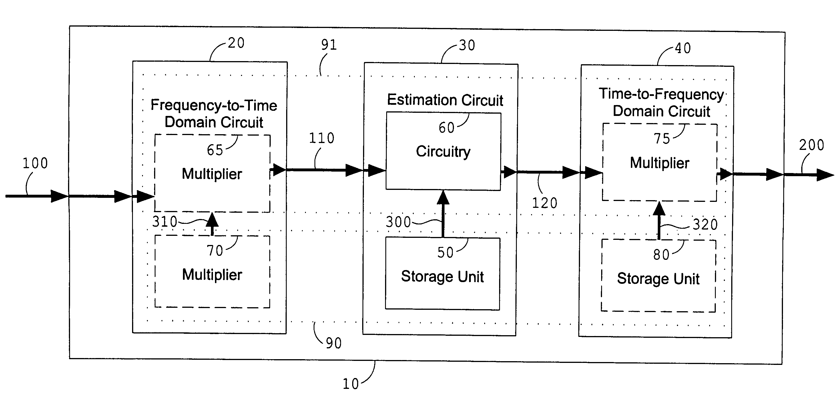
[0037]The invention explicitly uses the finite delay spread of the channel and develops a low complexity algorithm capable of estimating the channel from part of the carriers only. A deterministic model is introduced and therefrom the associated Maximum Likelihood estimator is derived. This ML estimator can be interpreted as a transformation from frequency domain to time domain and back to frequency. The actual estimation is done in the time domain, where the number of parameters (i.e. the channel length) is small. The estimator is obtained by minimizing a quadratic criterion, which, combined with the small number of parameters, leads to a low complexity algorithm. As such, an exact low complexity solution is obtained. The invention is applicable when reference tones are available for all Nc carriers of the multi-carrier channel but also when less reference tones are transmitted as in Pilot Symbol Assisted Modulation (PSAM). In an alternative formulation the invention can be casted ...
PUM
 Abstract
Description
Claims
Application Information