System and method for detecting obstacle

a detection system and obstacle technology, applied in the field of systems and methods for detecting obstacles, can solve the problems of expensive laser beam use, obstacle detection accuracy problem, and the inability to recognize a lane only by the sensor itsel

Active Publication Date: 2006-01-24
KK TOSHIBA
View PDF8 Cites 30 Cited by
  • Summary
  • Abstract
  • Description
  • Claims
  • Application Information

AI Technical Summary

Problems solved by technology

Utilization of a laser beam is expensive.
Utilization of an ultrasonic wave causes a problem in detection accuracy of an obstacle because of a low resolution of the ultrasonic wave.
In addition, with an active sensor utilizing a laser beam or an ultrasonic wave, recognition of a lane is impossible only by the sensor itself.
There are, however, many obstacles having similar brightness, color, and textures to those of the road to make it difficult to use the method for distinguishing the obstacle region and the road region.
In a normal stereoscopic viewing, there is a problem in that a process of carrying out matching is necessary.
The matching means a searching calculation necessitated when making a point being the same in the space into correspondence between right and left images with a problem of extremely high in calculation cost.
However, in the case where reflected images of an obstacle, structures around the road, and scenery of environment are produced on the road surface as observed in a wet road surface in rainy weather, it was impossible by the related procedure which was for detecting an object with a height other than zero to correctly detect an obstacle.

Method used


Image

  • System and method for detecting obstacle
  • System and method for detecting obstacle
  • System and method for detecting obstacle

Examples


Embodiment Construction

[0032]In the following, an example of the invention will be explained according to the drawings.

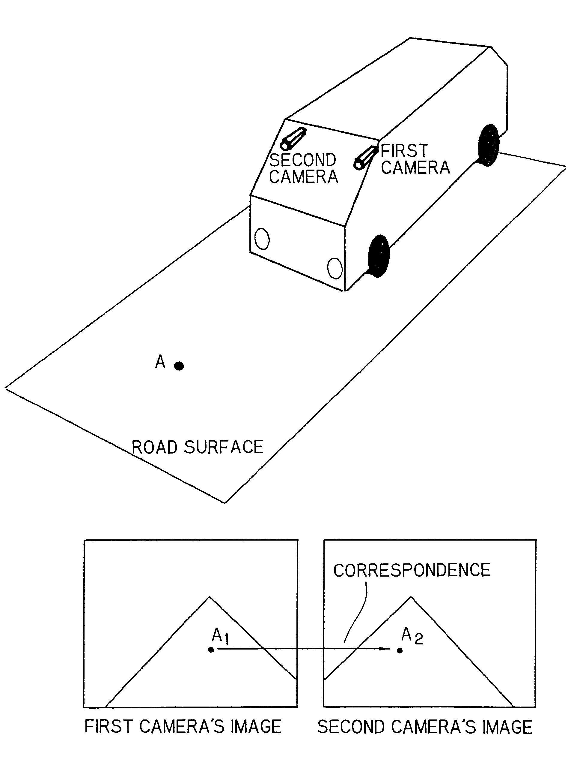
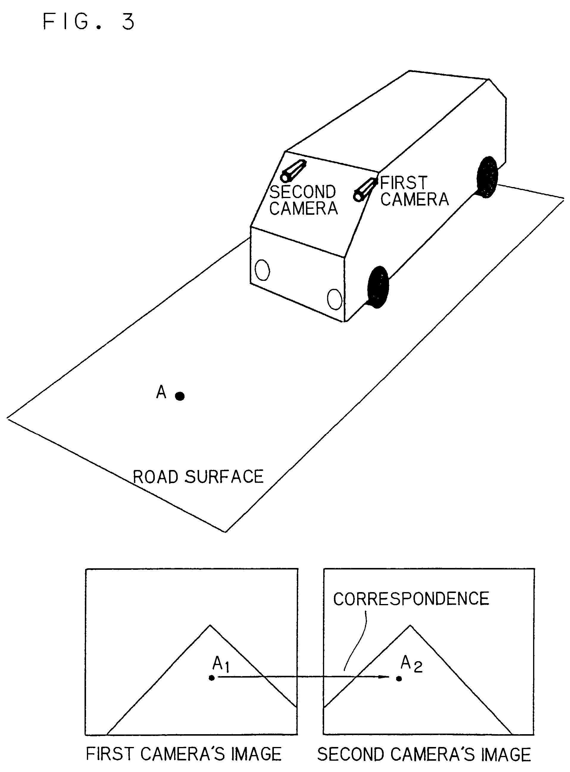
[0033]In the example, a situation is assumed under which a vehicle mounting a stereo camera including right and left cameras (the vehicle mounting the stereo camera is to be referred to as a subject vehicle) is running on a road surface (a reference plane) to detect obstacles such as vehicles going ahead and pedestrians.

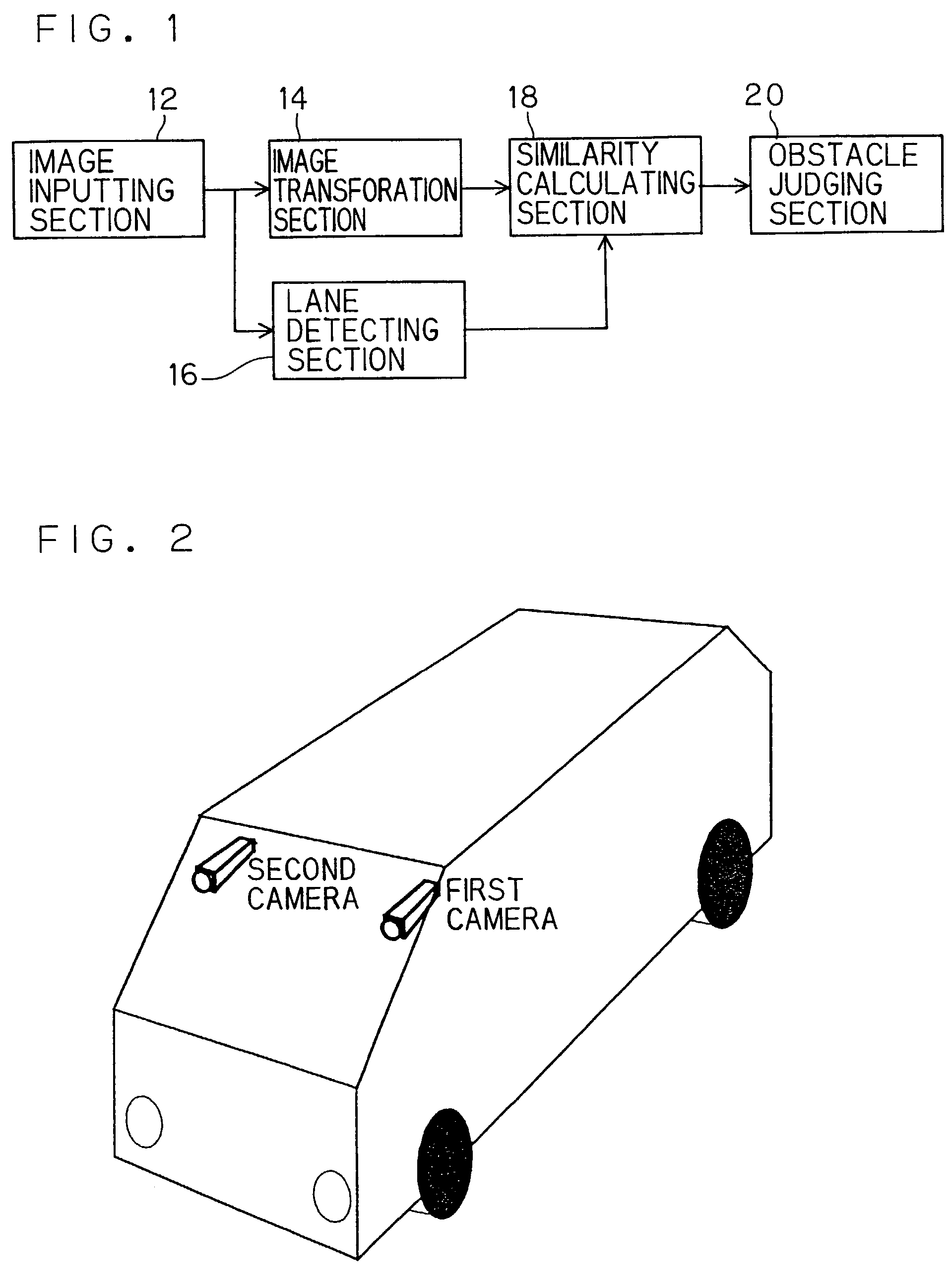
[0034]FIG. 1 shows a schematic arrangement of an obstacle detecting system 10 in the example, which includes an image capture section 12, an image transforming section 14, a lane detecting section 16, a similarity calculating section 18, and an obstacle judging section 20. In each of the sections, functions as explained below are realized by means of a program stored in a computer.

[0035]In the following, details of the sections will be explained.

(Image Capture Section 12)

[0036]The image capture section 12 functions to input images from two cameras (a stereo camera) secured...


PUM


Abstract

A system for realizing support of safety driving or automatic driving, in which a vehicle-mounted stereo camera is used to detect obstacles on a road surface even in the presence of a reflected image of an obstacle under a wet road condition. The system includes two cameras, an image transforming section transforming a first camera's image by image transform T that transforms any given pixel in a road surface region in the first camera's image to a corresponding pixel in a second camera's image, a lane detecting section detecting a traffic lane on a road on the basis of characteristics of the image obtained from the second camera, a similarity calculating section sequentially establishing processing regions, each having a base formed by one of image lines in a region within a lane, for carrying out inter-image arithmetic operations on the assumption that an obstacle stands from a contact line on a road surface as an image line, and obtaining respective degrees of similarity between the first cameras s image and the second camera's image and between the second camera's image and the transformed image, and an obstacle judging section detecting the object from a difference between the two kinds of degrees of similarity on the road region sequentially obtained.

Description

BACKGROUND OF THE INVENTION[0001]The present invention mainly relates to a system and a method for detecting an obstacle on a road such as a vehicle going ahead, a parking vehicle, or a pedestrian by vehicle-mounted camera system for realization of supporting safety driving of a vehicle or automatic running of a vehicle.[0002]Technologies for detecting an obstacle may be roughly classified into that of utilizing a laser beam or an ultrasonic wave, and that of utilizing a TV camera. Utilization of a laser beam is expensive. Utilization of an ultrasonic wave causes a problem in detection accuracy of an obstacle because of a low resolution of the ultrasonic wave. In addition, with an active sensor utilizing a laser beam or an ultrasonic wave, recognition of a lane is impossible only by the sensor itself.[0003]Compared with this, a TV camera is relatively inexpensive and also is suitable for detecting an obstacle in resolution, measuring accuracy, and a measurable range. A TV camera uti...

Claims


Application Information

Patent Timeline
Patent Type & Authority Patents(United States)
IPC IPC(8): G06K9/36G01C11/06G06T1/00G01S11/12G06K9/00G06T7/00G08G1/16
CPCG01C11/06G01S11/12G06K9/00805G08G1/16G06K9/00798G06T7/0024G08G1/166G08G1/167G06T7/30G06V20/588G06V20/58
Inventor TAKEDA, NOBUYUKIHATTORI, HIROSHIONOGUCHI, KAZUNORI
Owner KK TOSHIBA
Why Eureka
Try Eureka