
Modular paint oven

a module and oven technology, applied in the field of modules, can solve the problems of unnecessarily adding cost to the construction of the oven, affecting the operation of the oven, so as to achieve the effect of convenient manufacturing

Active Publication Date: 2006-01-31
DURR SYST INC
View PDF11 Cites 18 Cited by
  • Summary
  • Abstract
  • Description
  • Claims
  • Application Information

AI Technical Summary

Benefits of technology

[0006]It has been determined that the heavy structural members associated with prior art ovens are not necessary, primarily because the oven does not provide structural support but merely retains heat to cure the coating applied to the product. Therefore, the present invention provides a light weight alternative that is easily manufactured at a remote location and transferred to the location intended for use.

Problems solved by technology

Present designs include significant structural components that have proven to unnecessarily add cost to the construction of the oven.
These structural members, which are fashioned from heavy gauge steel, add a significant amount of material costs to the oven, which has proven unnecessary, particularly in light of increasing steel costs.
Thus, unnecessary structural components included in each module will add cost to the oven several times over.

Method used


Image

  • Modular paint oven
  • Modular paint oven
  • Modular paint oven

Examples


Embodiment Construction

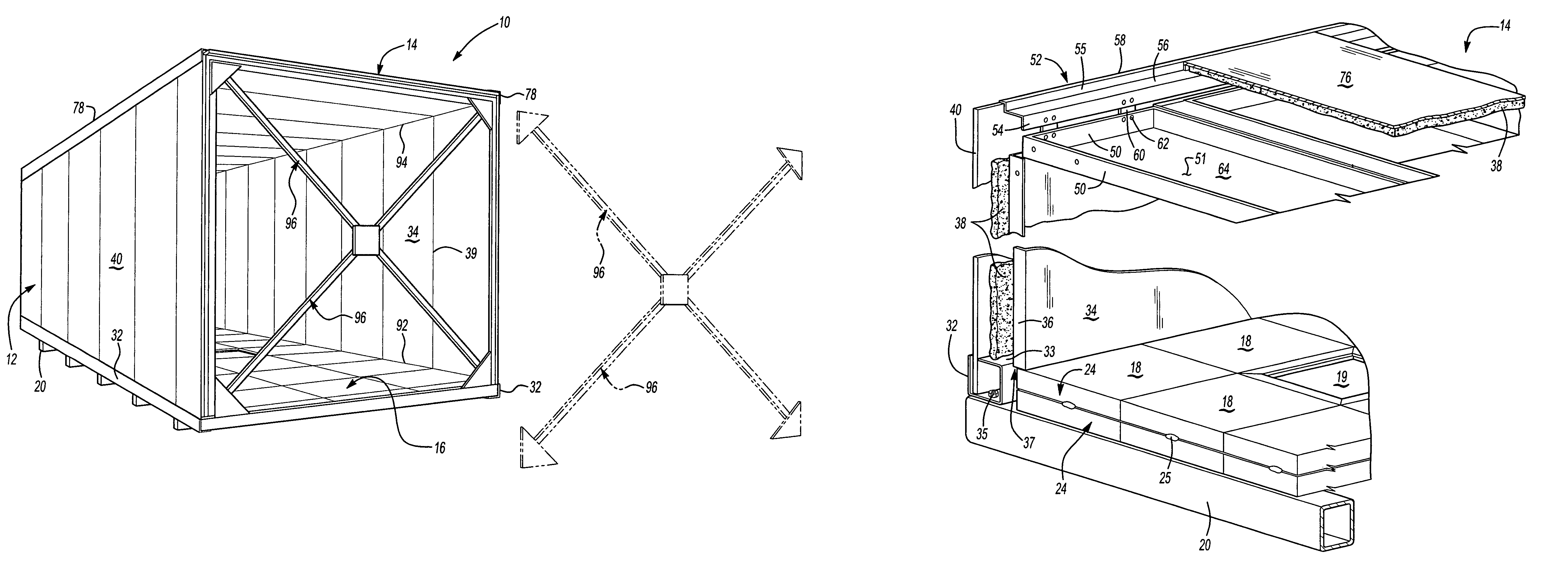
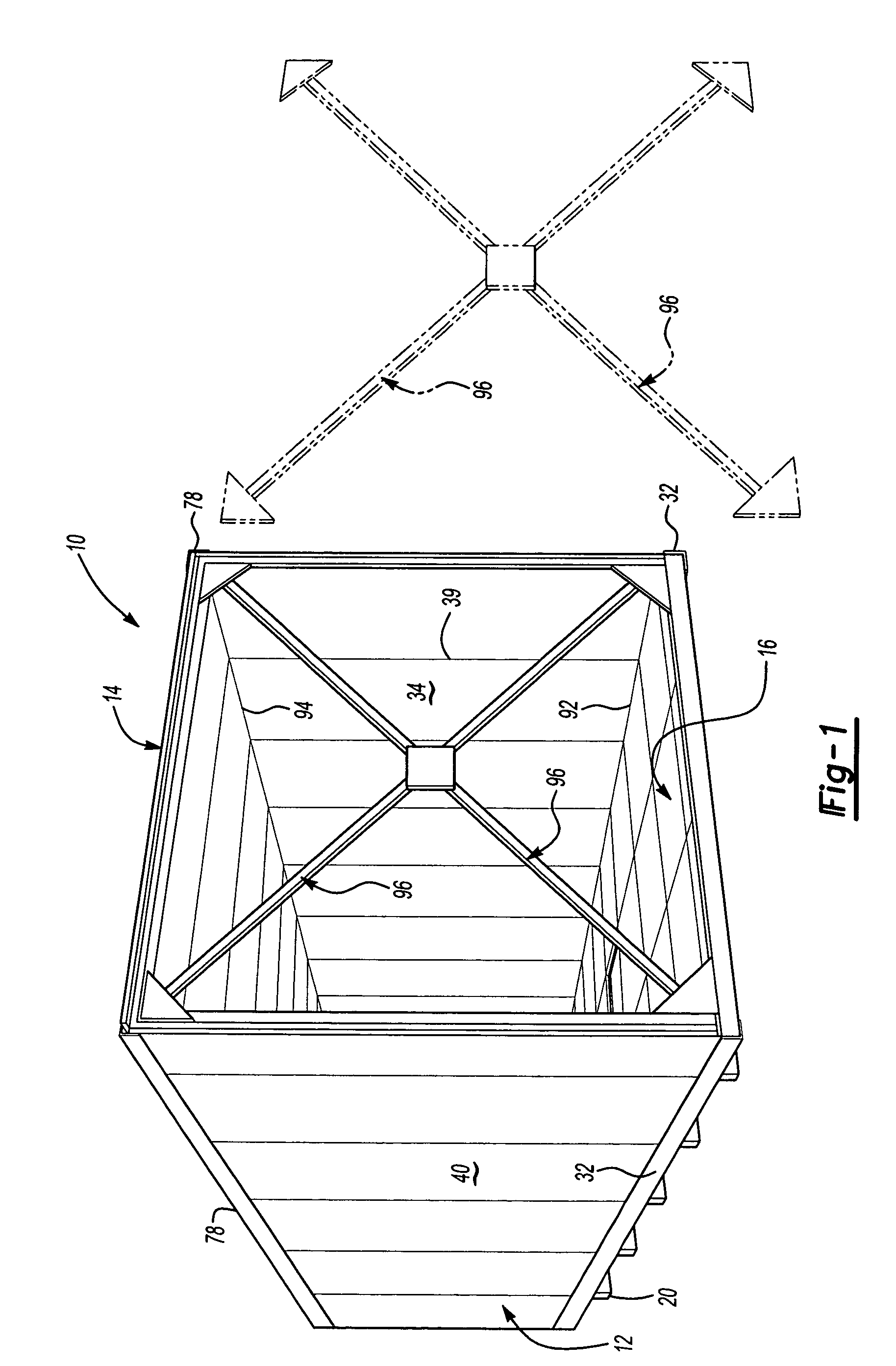
[0016]An oven module of the present invention is generally shown at 10 in FIG. 1. The module 10 includes side walls 12, a roof 14, and a floor 16.

[0017]As best shown in FIGS. 2A and 2B, the floor is fabricated from a plurality of floor modules 18. The floor modules 18 are generally rectangular in shape and preferably are arranged longitudinally with respect to the length of the oven module 10. Preferably, three rows of floor modules 18 are positioned in an abutting relationship to form the entirety floor 16 (see also FIG. 1). The floor modules 18 are supported by support member 20 that extend across the width of the oven module 10 preferably positioned beneath the seam 22 formed between abutting floor modules 18. A hot air inlet 19 is disposed in the floor 16, the purpose of which will be explained further below.

[0018]Each floor module 18 is formed from two floor panels 24, one of which is best represented in FIG. 2B. Each floor panel 24 includes a panel base 26 having an upward ext...


PUM


Abstract

An oven assembly for drying paint on a product transported by a conveyor includes a plurality of modules positioned in a generally abutting relationship. Each of the modules includes a roof, side walls, and a floor having a length and a width. The floor is formed from abutting floor panels reinforced by a plurality of support members spaced along the length of the floor and having a length greater than the width of the floor. The side walls include an inner side wall panel disposed in an overlapping relationship with the floor and a side wall cladding panel supported by the support members along the width of the floor thereby concealing thermal insulating material disposed between the inner side wall panel and the side wall cladding panel.

Description

RELATED APPLICATIONS[0001]This application claims priority to U.S. Provisional Patent Application No. 60 / 453,560 filed Mar. 11, 2003.BACKGROUND OF THE INVENTION[0002]Automotive and industrial paint are typically baked at temperatures between 200 and 400° F. in ovens positioned at the end of paint application booths in production painting facilities. These ovens typically include an oven housing that encloses heating apparatus for applying either radiant or convection heating as is known to those of skill in the art.[0003]Preferably, these ovens are constructed from modules that are manufactured at a fabricating facility and transferred to the production paint facility. The modules are then affixed together to form the oven housing through which a conveyor transfers the products that have been painted. A typical module includes side walls, a roof and a floor, and has a length of between about 20 and 40 feet. Thermal insulation is sandwiched between inner and outer panels to prevent h...

Claims


Application Information

Patent Timeline
IPC IPC(8): F26B25/06F26B25/08
CPCF26B25/06F26B25/08F26B2210/12
Inventor ROESLER, BRUCECOOK, LAWRENCE A.SMITH, DOUGLAS G.COLE, DAVID J.ANDREWS, JEFFREY C.
Owner DURR SYST INC
Learn More