
System support assembly

a technology of system support and assembly, which is applied in the direction of auxilary members of forms/shuttering/falseworks, building repairs, walls, etc., can solve the problems of icf wall buckle, take an entire crew of construction workers to properly pour concrete, etc., and achieve the effect of convenient us

Inactive Publication Date: 2006-01-31
INGRID C GREEN
View PDF16 Cites 29 Cited by
  • Summary
  • Abstract
  • Description
  • Claims
  • Application Information

AI Technical Summary

Benefits of technology

[0015]Still yet, another object of the present invention is to provide a system support assembly that is easy to use.

Problems solved by technology

While suited for their intended purposes, many disadvantages exist with the current system of stacking ICFs and pouring concrete therein when constructing a foundation for a structure.
Further, only experienced contractors in the art of construction can successfully construct a foundation using ICFs.
Further, it takes an entire crew of construction workers to properly pour the concrete.
Another disadvantage, which can occur when pouring concrete, is that the ICF wall may buckle due to the weight of the concrete.

Method used


Image

  • System support assembly
  • System support assembly
  • System support assembly

Examples


Embodiment Construction

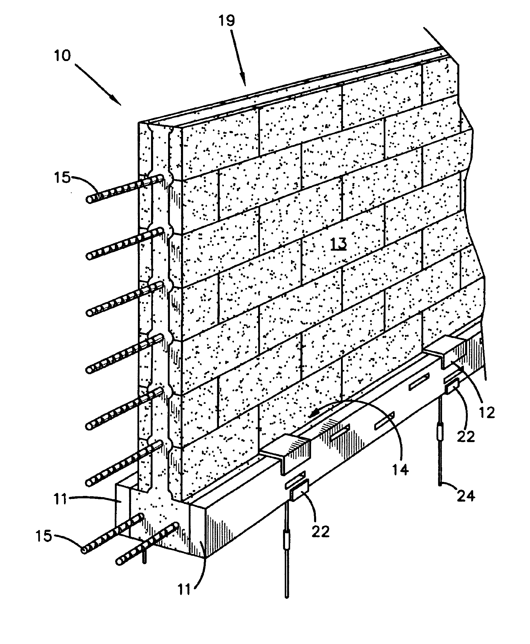
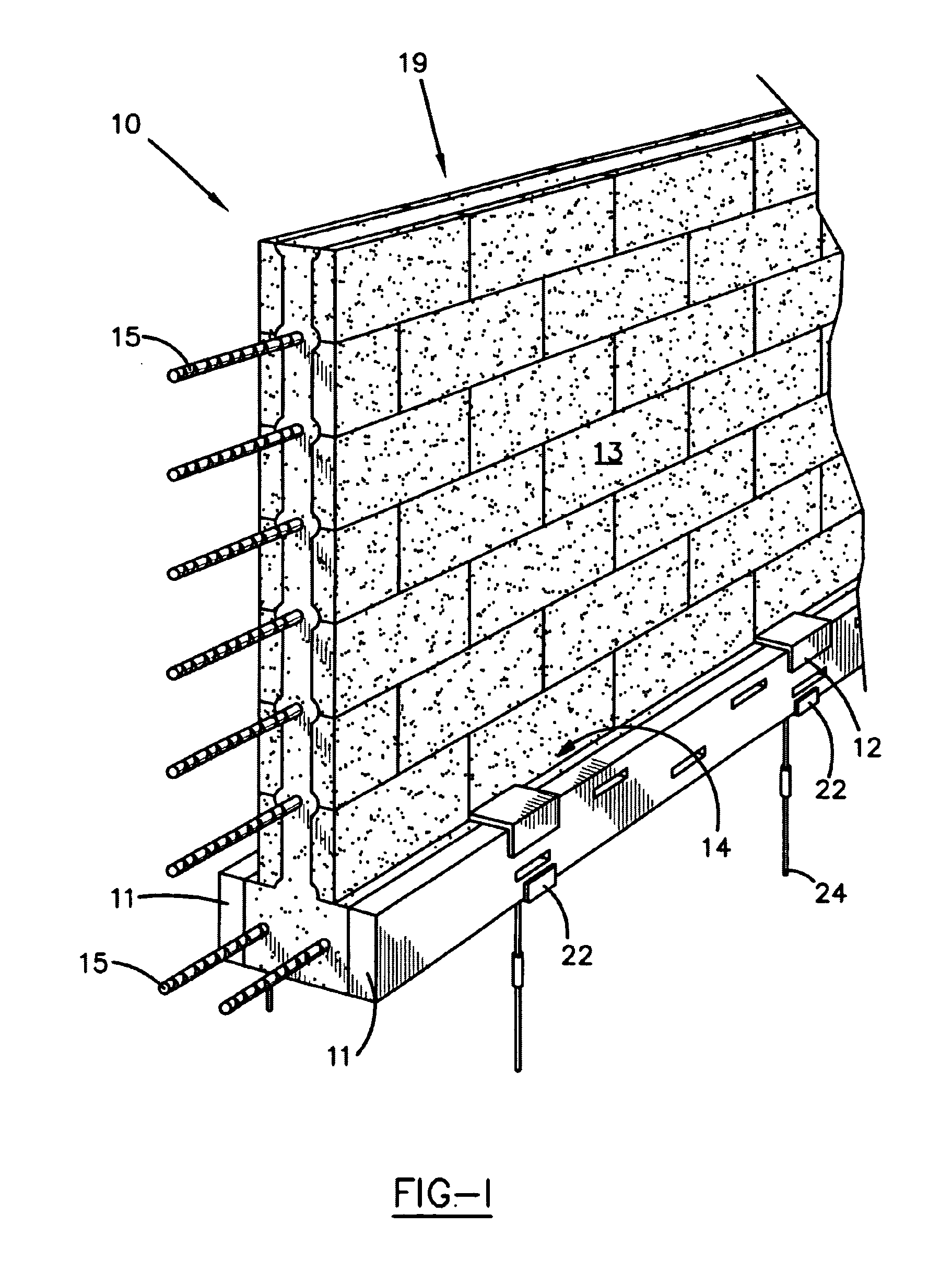
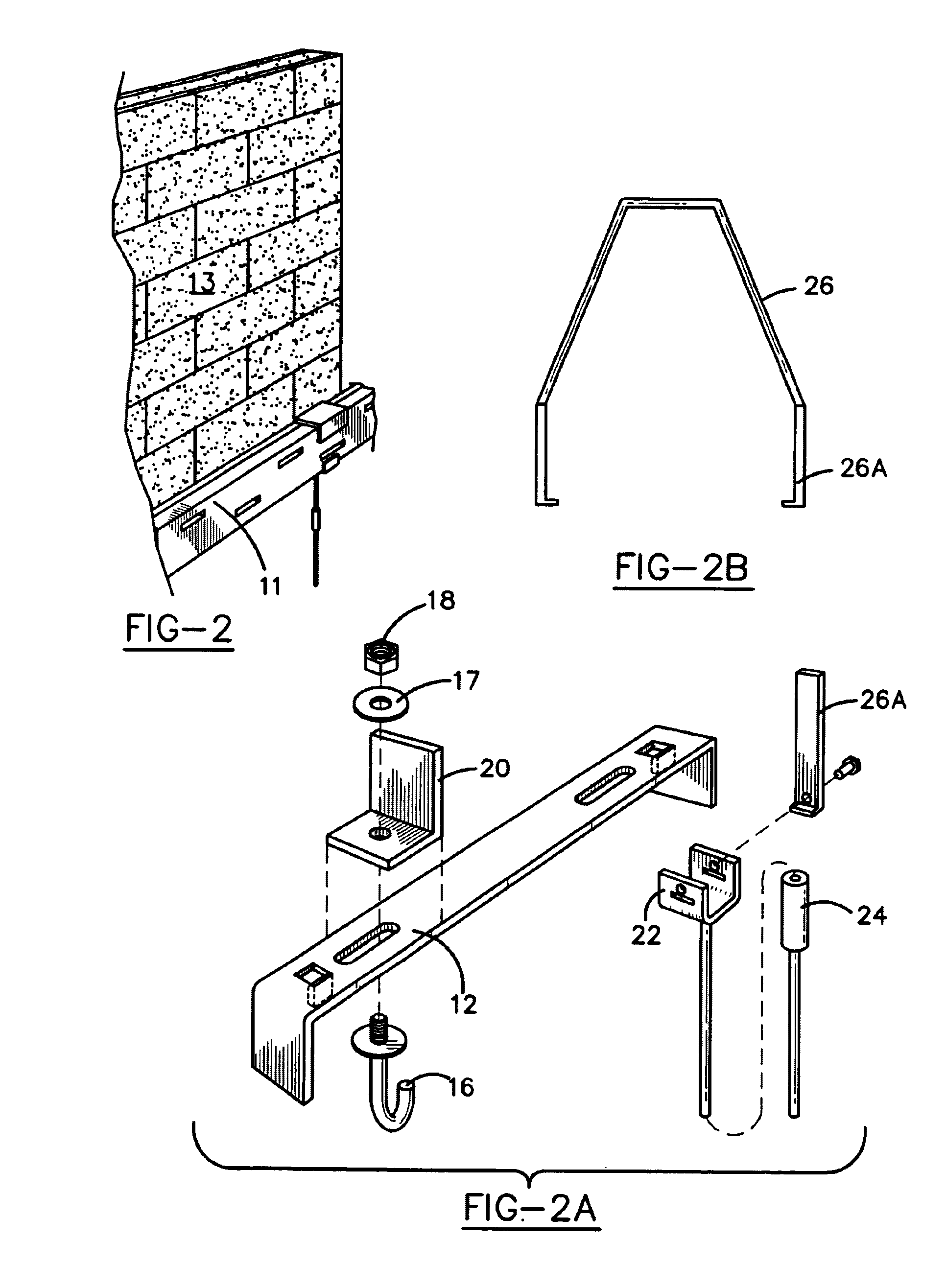
[0026]Turning to FIGS. 1-3, a system support assembly 10 is shown. Generally, the system support assembly comprises footer means, such as a pair of footer forms 11, insulated concrete forms (ICF) 13, footer form base saddles 22, a poly form saddle assembly 14 and first and second vertical stabilizers 26a, 26b. Although, the present invention is described to be used with ICFs, any other structure utilizing block-like units may take advantage of the system support assembly 10, including without limitation, brick laying or other concrete forms. The footer form base saddle 22 may be generally u-shaped and is driven into the ground forming two substantially parallel areas. Each footer form 11 is placed within the footer form base saddles 22 such that a cavity is defined therebetween which will ultimately form the footer of the foundation. The poly form saddle assembly 14 comprises a poly form saddle 12 and fasteners 16, 17, 18. The poly form saddle 12 may also be generally u-shaped and i...


PUM


Abstract

A system support assembly comprises a pair of substantially parallel footer forms, insulated concrete forms, footer form base saddles, a poly form saddle assembly and first and second vertical stabilizers. The footer form base saddle may be generally u-shaped and is driven into the ground forming two substantially parallel areas. Each footer form is placed within the row formed by the footer form base saddles such that a cavity is defined therebetween which will ultimately form the footer of the foundation. The poly form saddle assemble comprises a poly form saddle and fasteners. The poly form saddle may also be generally u-shaped and is placed over both footer forms, thus straddling the same. The poly form saddle may then be secured with corresponding fasteners. The insulated concrete forms are placed side by side and are stacked upward, such that a wall is formed. A first poly form vertical stabilizer is placed over the wall and operatively connected to the footer form base saddle. More insulated concrete forms are stacked to complete the wall. The second poly form vertical stabilizer may then be placed, preferably laterally spaced from the first poly from vertical stabilizer. The second poly form vertical stabilizer is also operatively connected to the footer form base saddle. Then, the concrete is poured into the insulated concrete forms such that the foundation wall and footers are poured and cured at one time.

Description

[0001]This application claims priority from a Provisional Patent Application having Ser. No. 60 / 253,697, which was filed on Nov. 27, 2000.BACKGROUND OF THE INVENTION[0002]1. Field of Invention[0003]This invention pertains to a system support assembly. More specifically the present invention relates to the art of methods and apparatuses for securing concrete forms used during construction of foundations.[0004]2. Description of the Related Art[0005]In the art of constructing buildings, foundations are poured. Normally, a wood structure form is used where a contractor places wood inside and outside a concrete split between them. Footers are poured first, which require mounting brackets, rebar and other supports ordinarily used in construction in order to put the foundation blocks on the footers and keep the foundation blocks from moving side to side. After the footers are poured and cured, the foundation walls are poured.[0006]Currently existing in the art for foundation walls are insu...

Claims


Application Information

Patent Timeline
IPC IPC(8): E04B2/00E04G11/06E02D27/02E04B2/86E04C5/18
CPCE02D27/02E04C5/18E04B2/86E04B2002/8688E04G17/002
Inventor CLAPP, GEORGE W.
Owner INGRID C GREEN
Learn More