Internal combustion engine

a combustion engine and internal combustion technology, applied in the direction of machines/engines, electric control, ignition automatic control, etc., can solve the problems of poor ignitability and inability to achieve predetermined performance, poor anti-knock property of ron fuel, etc., and achieve the effect of sufficient performan

Active Publication Date: 2006-01-31
TOYOTA JIDOSHA KK
View PDF21 Cites 205 Cited by
  • Summary
  • Abstract
  • Description
  • Claims
  • Application Information

AI Technical Summary

Benefits of technology

[0008]In the internal combustion engine having the above structure, the actual fuel mixing ratio of the fuel fed to a cylinder is accurately calculated by subtracting the stuck-on-wall fuel quantity from the quantity of fuel injected from each fuel injection means so that the target mixing ratio is achieved.
[0010]In the internal combustion engine having the above structure, the actual fuel mixing ratio of the fuel fed to a cylinder is accurately calculated based on the flow rate of the fuel fed to each fuel injection means, which is detected by the fuel flow rate detecting means.
[0012]In the internal combustion engine having the above structure, the execution ignition timing corresponding to the actual fuel mixing ratio is set and, accordingly, the performance can be sufficiently achieved.

Problems solved by technology

The low RON fuel has a good ignitability and a poor antiknock property, and the high RON fuel has a poor ignitability and a good antiknock property.
However, the fuel infected from the fuel injector can stick to an intake port and, accordingly, a divergence, between the mixing ratio of the fuel actually fed to a combustion chamber and the target fuel mixing ratio, occurs.
Therefore, if a divergence, between the mixing ratio of the fuel actually fed to a combustion chamber and the target fuel mixing ratio, occurs a predetermined performance cannot be achieved.

Method used


Image

  • Internal combustion engine
  • Internal combustion engine
  • Internal combustion engine

Examples


first embodiment

[0035]The control operation of the present invention having the above-described hardware structure will be described below.

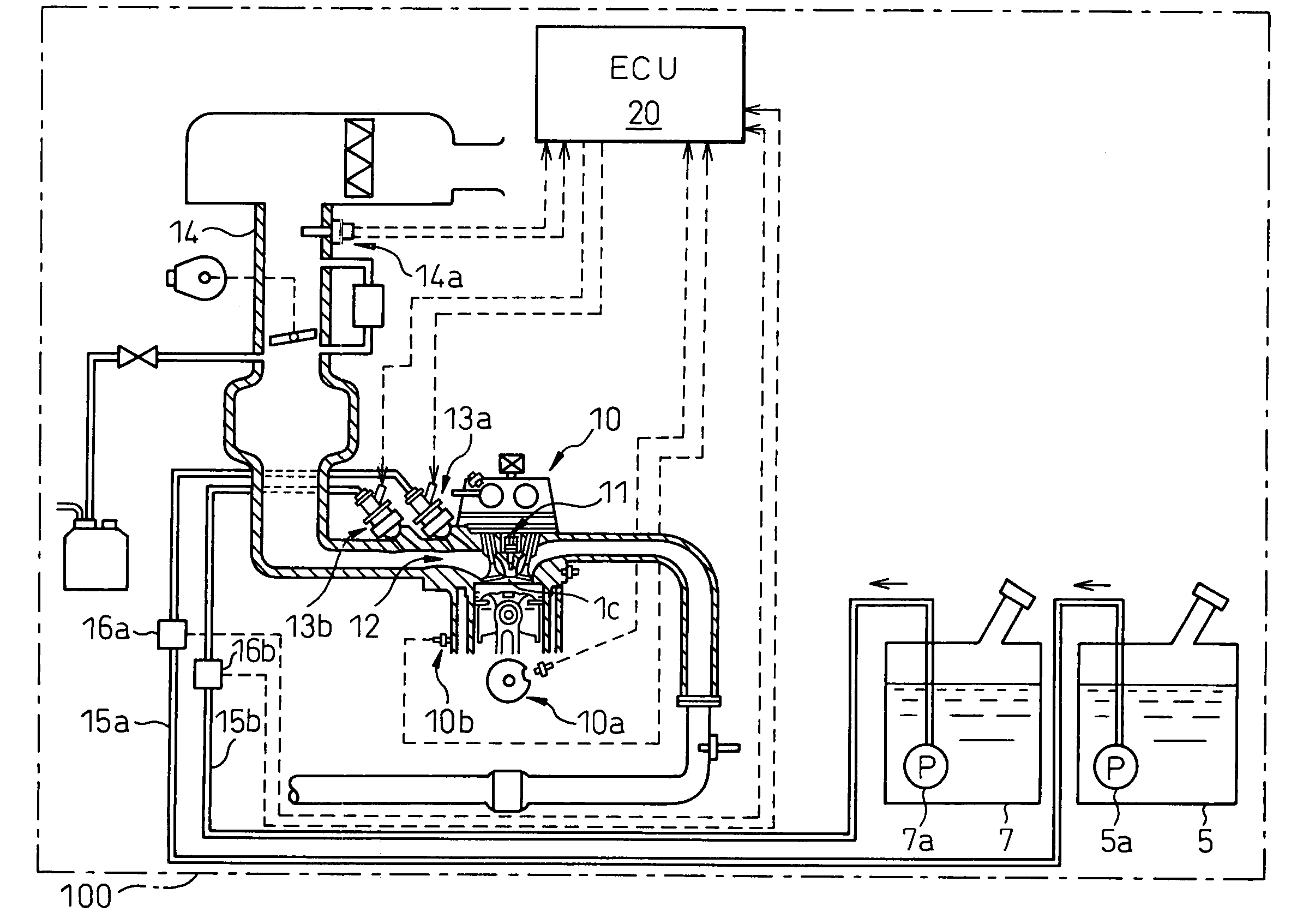
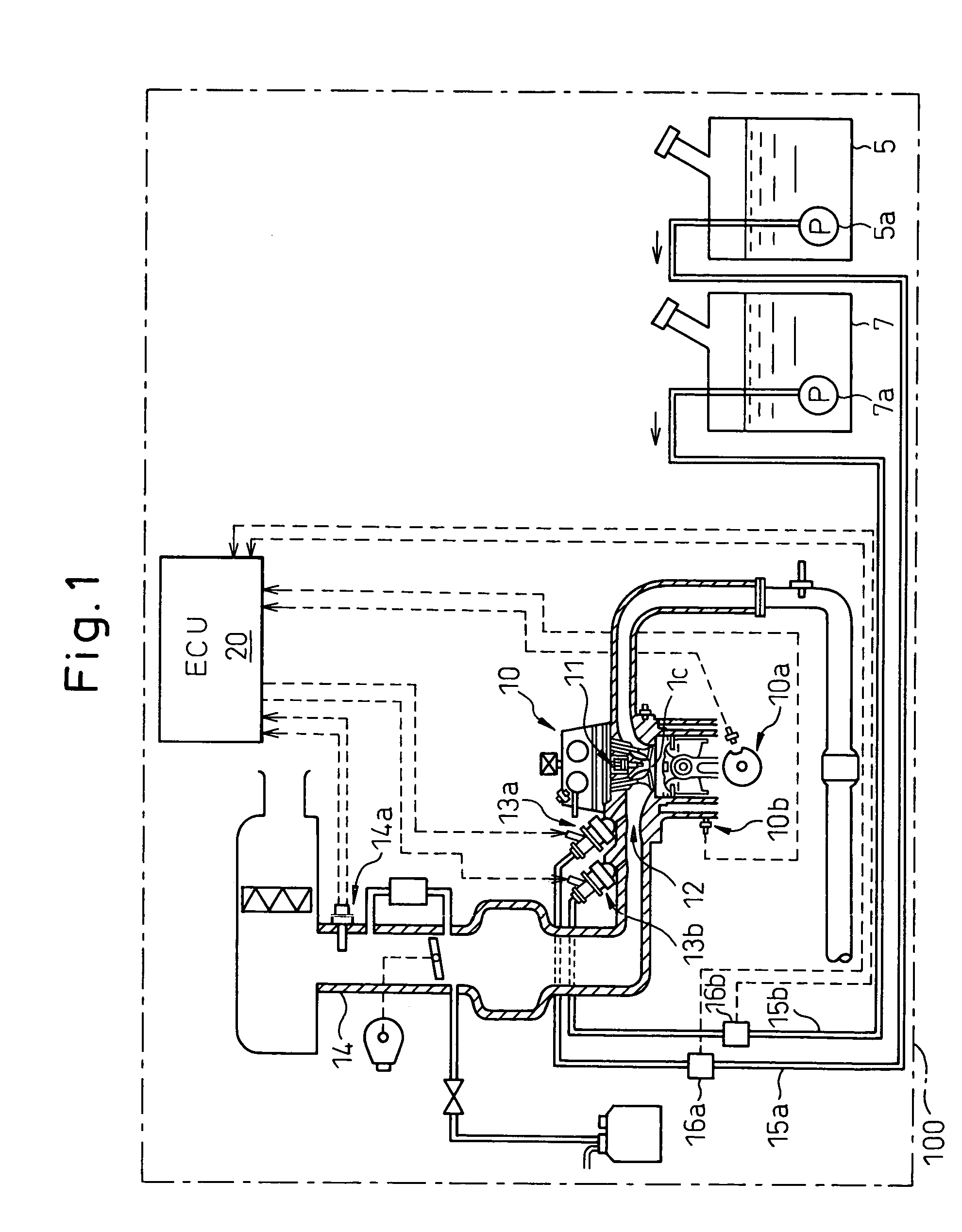
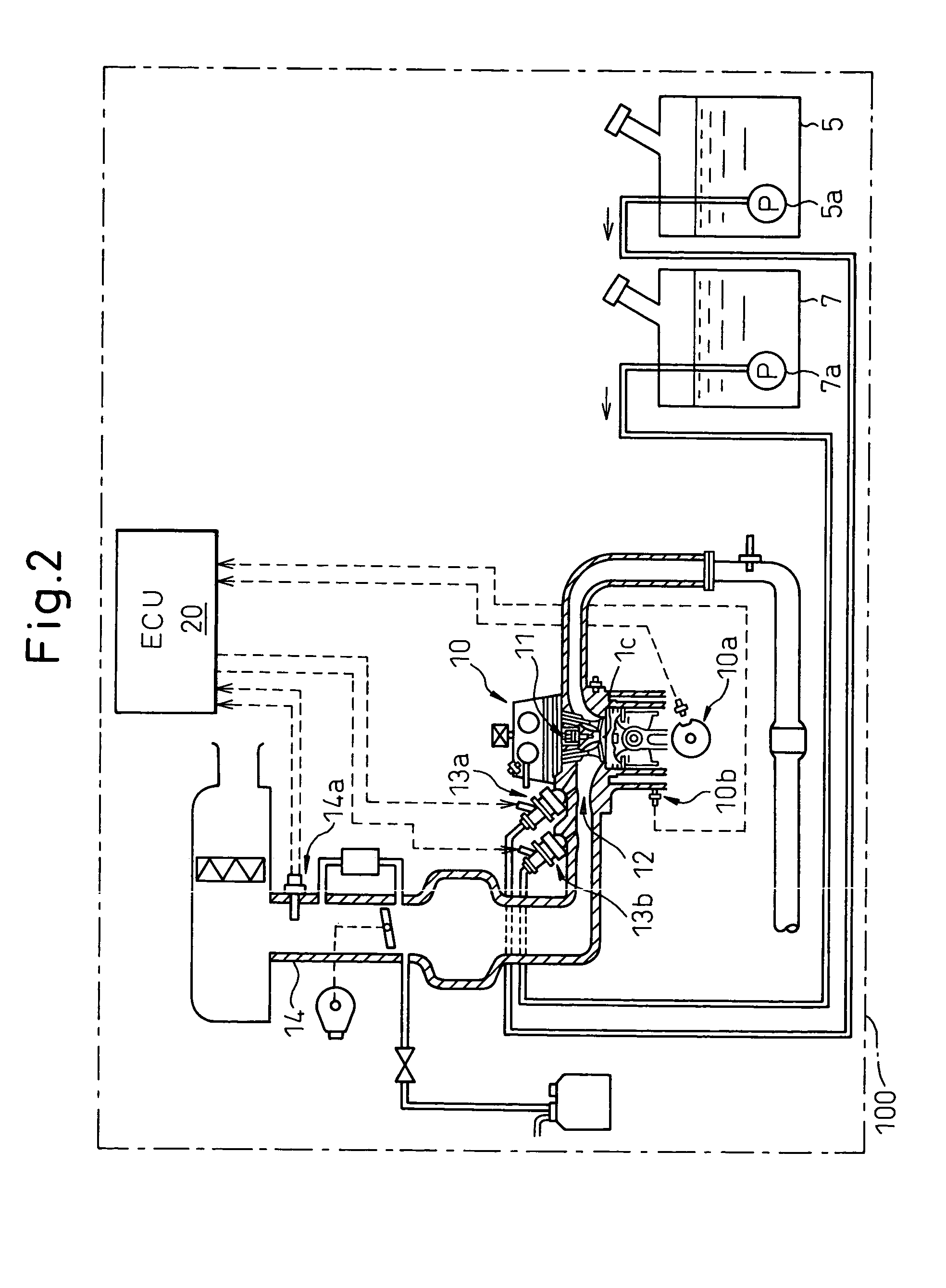
[0036]First, the outline of the control operation will be described. In the first embodiment, a difference between an actual fuel mixing ratio AFMIX and a target fuel mixing ratio TFMIX, i.e., a fuel mixing ratio difference DFMIX is obtained and then, an execution ignition timing is corrected based on the fuel mixing ratio difference DFMIX. The actual fuel mixing ratio AFMIX is obtained from a flow rate FL1 of the low RON fuel, detected by the first fuel flow meter 16a and a flow rate FL2 of the high RON fuel, detected by the second fuel flow meter 16b. The target fuel mixing ratio TFMIX is obtained from a map based on an intake air flow rate GA as a load of an engine speed NE.

[0037]With regard to the ignition timing, basically, the execution ignition timing SA is obtained by adding a corrective ignition advance KSA to advance the ignition timing to a knocking l...

second embodiment

[0045]In the second embodiment, the actual fuel mixing ratio AFMIX is obtained by subtracting the stuck-on-wall fuel quantities LW1 and LW2 (obtained from a map), for the intake pipe 12, from the injection fuel quantity TAU1 of the first fuel injector 13a and the injection fuel quantity TAU2 of the second fuel injector 13b, respectively. If a negative pressure is large, during coasting or the like, fuel stuck to an intake pipe wall surface is drawn in the cylinder. Thus, the stuck-on-wall fuel quantities LW1, LW2 are negative values and, accordingly, not subtraction but addition of LW1 and LW2 is actually executed.

[0046]FIG. 4 is a flowchart of the second embodiment in which the above-described control operation is carried out. Steps 401 to 403 are identical to the steps 301 to 303 in the flowchart of the first embodiment. At steps 404, 405, the injection fuel quantity TAU1 of the first fuel injector 13a and the injection fuel quantity TAU2 of the second fuel injector 13b are read. ...


PUM


Abstract

An internal combustion engine, in which multiple kinds of fuels are fed to a cylinder from multiple fuel injectors each corresponding to each of multiple kinds of fuels at a target mixing ratio determined according to a running condition, includes an actual fuel mixing ratio calculator calculating an actual fuel mixing ratio of fuel fed to cylinder. The actual fuel mixing ratio calculator at first calculates actual fuel injection quantity of each fuel injection by adding or subtracting predetermined stuck-on-wall fuel to or from each quantity of fuel injected from each fuel injector, and then calculates an actual fuel mixing ratio of fuel fed to cylinder on the basis of the calculated actual fuel injection quantity of each fuel injector.

Description

BACKGROUND OF THE INVENTION[0001]1. Field of the Invention[0002]The present invention relates to an internal combustion engine in which a high RON fuel and a low RON fuel are mixed and fed to a combustion chamber, wherein high RON fuel means high octane number fuel, and low RON fuel means low octane number fuel.[0003]2. Description of the Related Art[0004]The low RON fuel has a good ignitability and a poor antiknock property, and the high RON fuel has a poor ignitability and a good antiknock property. Accordingly, an internal combustion engine in which the low RON fuel is stored in a low RON fuel tank and the high RON fuel is stored in a high RON fuel tank, and the low RON fuel and the high RON fuel are fed to a combustion chamber at a mixing ratio appropriate to a driving condition is well known and is disclosed in, for example, Japanese Unexamined Patent Publication (Kokai) No. 2001-50070.[0005]In the internal combustion engine described in Japanese Unexamined Patent Publication (...

Claims


Application Information

Patent Timeline
Patent Type & Authority Patents(United States)
IPC IPC(8): F02B7/00F02D19/08F02P5/15F02D37/02F02D41/00F02D41/04F02D45/00F02M43/00F02P5/152
CPCF02D19/0628F02D19/081F02D37/02F02D41/0025F02D41/047F02M43/00F02P5/1527F02D19/0649F02D19/0692F02B2275/16Y02T10/36Y02T10/46Y02T10/123F02D2200/0614Y02T10/12Y02T10/30Y02T10/40
Inventor NIIMI, KUNIAKI
Owner TOYOTA JIDOSHA KK
Why Eureka
Try Eureka