Conveyor chain

Inactive Publication Date: 2006-01-31
FROST TECH
View PDF13 Cites 43 Cited by
  • Summary
  • Abstract
  • Description
  • Claims
  • Application Information

AI Technical Summary

Benefits of technology

[0006]The present invention is intended to provide enhanced flexibility of chain links and enhanced relative movement between the chain

Problems solved by technology

The relative movement of the links and the pins or bolts leads to wear on the components and may eventually lead to a failure of the links and/or the pins or bolts.
The wear may increase if the friction between the pin and the links increases, such as due

Method used


Image

  • Conveyor chain
  • Conveyor chain
  • Conveyor chain

Examples


Embodiment Construction

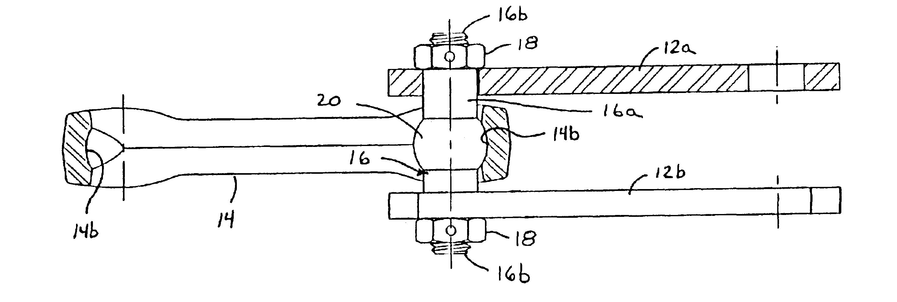
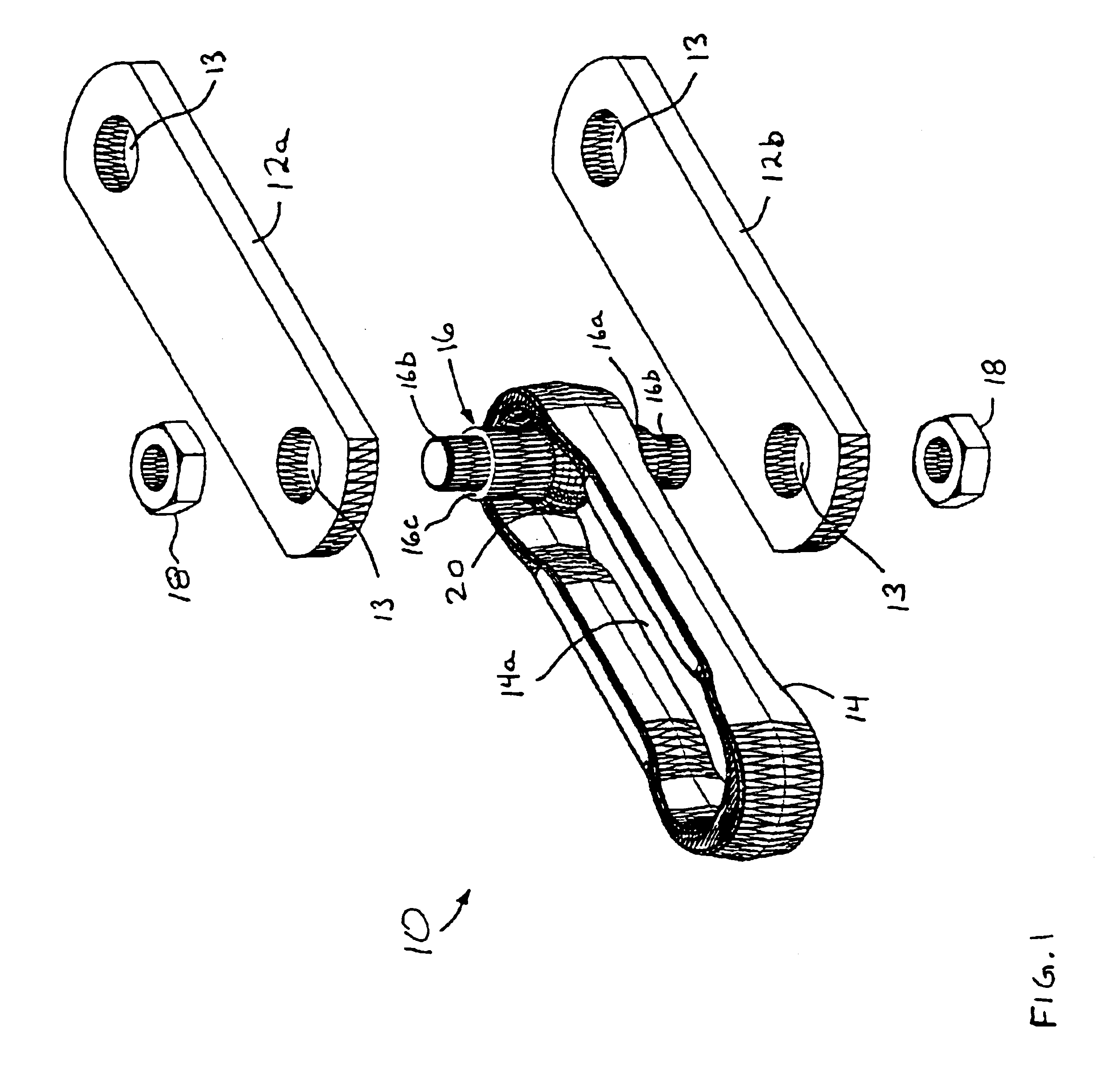
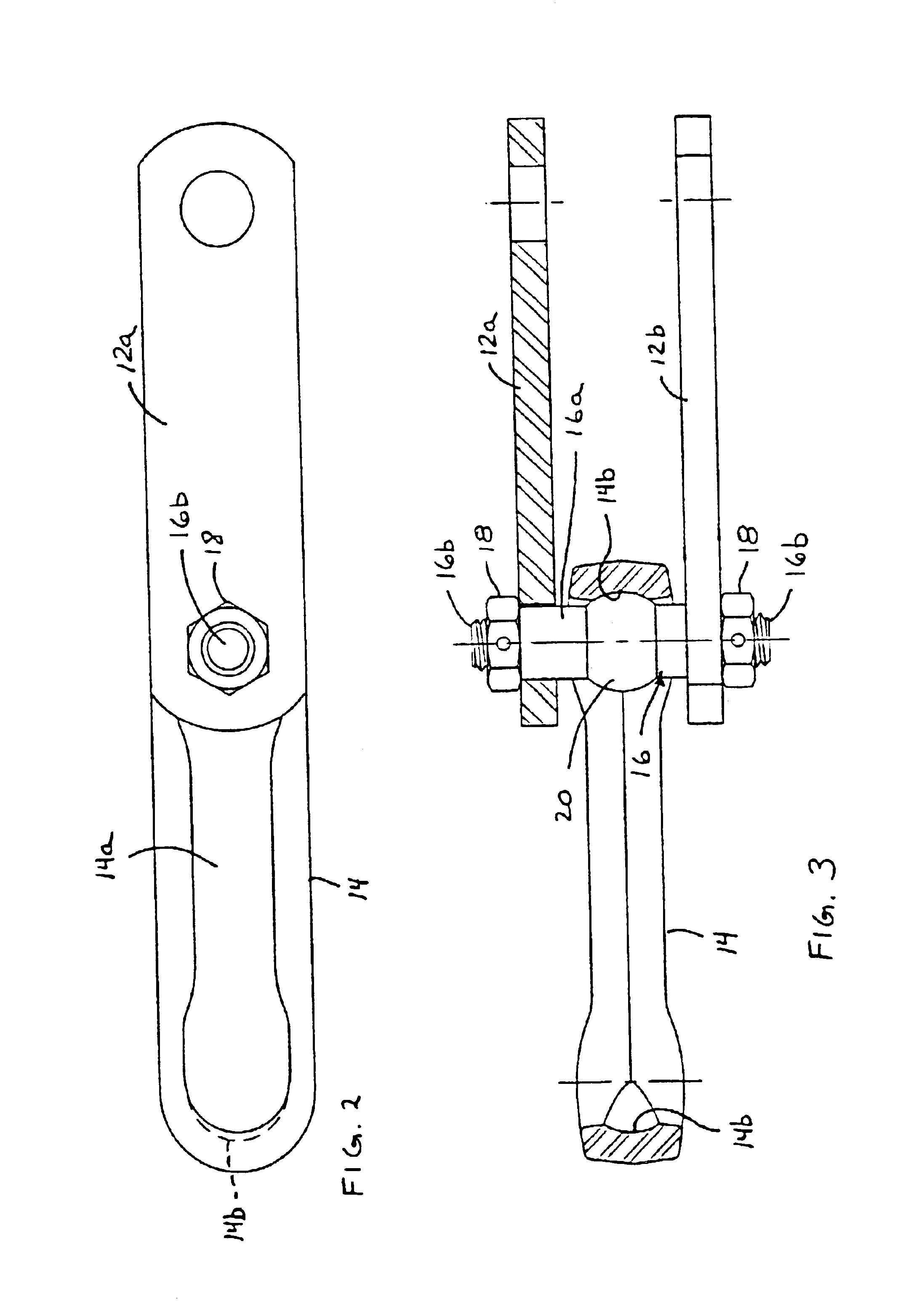
[0070]Referring now to the drawings and the illustrative embodiments depicted therein, a chain or section of chain 10 for conveying product along a conveying system, such as for material handling or processing systems or the like, includes a pair of side links 12a, 12b and a center link 14 (FIGS. 1-3). The center link 14 is retained between the side links 12a, 12b by a double ended stud or stud type pin 16, which extends through a center region 14a of center link 14 and through an opening 13 in each side link 12a, 12b and is retained therein by a corresponding fastener or nut 18. Stud 16 includes a generally spherical or toroidal-shaped ball member 20 positioned generally at a mid-point or mid-region of a shaft portion 16a of stud 16. Chain 10 includes multiple linkages connected together in a continuous loop about a conveying system, as is known in the art. For ease of description, only one section or set of linkages of the chain is shown and described herein, with the other linkag...


PUM


Abstract

A section of chain for conveying product along a material handling system includes a pin connecting a center link between two side links. The pin may have a sleeve portion around and at least partially along the shaft portion of the pin. The sleeve portion may engage a center link of the section of chain and may be movable relative to the shaft portion. The sleeve portion may comprise a polymeric material. The sleeve portion may be molded over an I-pin or the like, or may be slid or pressed onto a stud-ended pin or bolt or the like. The pin may include a generally spherical-shaped ball member or portion on the shaft portion to enhance flexibility of the section of chain. The pin may be dialable or selectably positioned at the side links to control and adjust the wear surface of the pin relative to the chain links.

Description

CROSS REFERENCE TO RELATED APPLICATIONS[0001]The present application claims priority of U.S. provisional application Ser. No. 60 / 362,751, filed Mar. 8, 2002 by Frost; U.S. provisional application Ser. No. 60 / 367,390, filed Mar. 25, 2002 by Frost; U.S. provisional application Ser. No. 60 / 381,518, filed May 17, 2002 by Frost; and U.S. provisional application Ser. No. 60 / 425,577, filed Nov. 12, 2002 by Frost, which are all hereby incorporated herein by reference in their entireties.FIELD OF THE INVENTION[0002]The present invention relates generally to chains for a conveying system and, more particularly, to bolted or pinned chains which allow for pivotable movement between a center link and a pair of side links about an axis defined by a bolt or pin extending therethrough.BACKGROUND OF THE INVENTION[0003]Chains for power transmission or for material handling and processing systems, such as, for example, chains which function to move a plurality of trolleys or the like along a path in a...

Claims


Application Information

Patent Timeline
IPC IPC(8): B65G17/06B65G17/40B65G17/38F16G13/06F16G13/10
CPCB65G17/38F16G13/10F16G13/06
Inventor FROST, CHARLES C.
Owner FROST TECH
Why Eureka
Try Eureka