Bioptical laser scanning system providing 360° of omnidirectional bar code symbol scanning coverage at a point of sale (POS) station

a bioptical laser scanning and pos technology, applied in the field of holographic laser scanners, can solve the problems of insufficient optimization of laser scanning patterns of prior art bioptical laser scanning systems in terms of scanning coverage and performance, inability to optimize laser scanning patterns of prior art bioptical laser scanning systems in general, and inability to accurately detect the astigmatic difference between visible laser diodes, etc., to achieve effective elimination of the inherent astigmatic difference in each visible laser diode, elimination or minimizing

Inactive Publication Date: 2006-01-31
METROLOGIC INSTR INC
View PDF92 Cites 18 Cited by
  • Summary
  • Abstract
  • Description
  • Claims
  • Application Information

AI Technical Summary

Benefits of technology

[0014]Accordingly, a primary object of the present invention is to provide a novel bioptical-type holographic laser scanning system which is free of the shortcomings and drawbacks of prior art bioptical laser scanning systems and methodologies.

Problems solved by technology

In general, prior art bioptical laser scanning systems are generally more aggressive that conventional single scanning window systems.
While prior art bioptical scanning systems represent a technological advance over most single scanning window system, prior art bioptical scanning systems in general suffered from various shortcomings and drawbacks.
Also, the laser scanning patterns of prior art bioptical laser scanning systems are not optimized in terms of scanning coverage and performance, and are generally expensive to manufacture by virtue of the large number of optical components presently required to constructed such laser scanning systems.

Method used


Image

  • Bioptical laser scanning system providing 360° of omnidirectional bar code symbol scanning coverage at a point of sale (POS) station
  • Bioptical laser scanning system providing 360° of omnidirectional bar code symbol scanning coverage at a point of sale (POS) station
  • Bioptical laser scanning system providing 360° of omnidirectional bar code symbol scanning coverage at a point of sale (POS) station

Examples


Embodiment Construction

[0314]Referring to the figures in the accompanying Drawings, the various illustrative embodiments of the bioptical holographic laser scanner of the present invention will be described in great detail.

[0315]In the illustrative embodiments, the apparatus of the present invention is realized in the form of an automatic code symbol reading system having a high-speed bioptical holographic laser scanning mechanism as well as a scan data processor for decode processing scan data signals produced thereby. However, for the sake of convenience of expression, the term “bioptical holographic laser scanner” shall be used hereinafter to denote the bar code symbol reading system which employs the bioptical holographic laser scanning mechanism of the present invention.

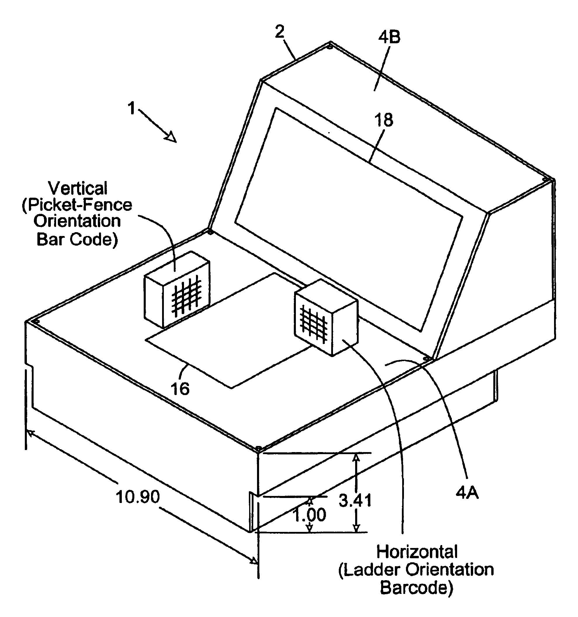
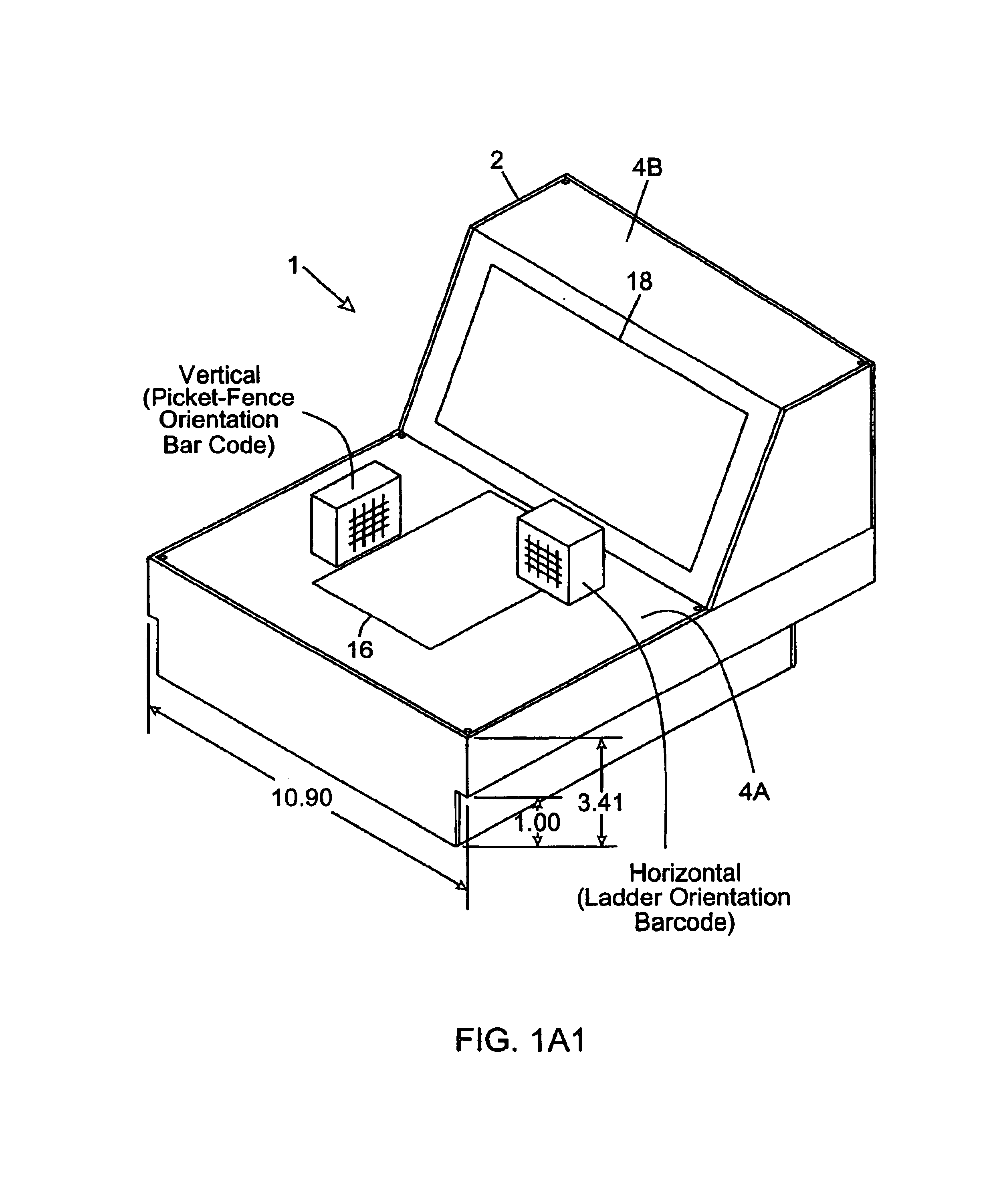
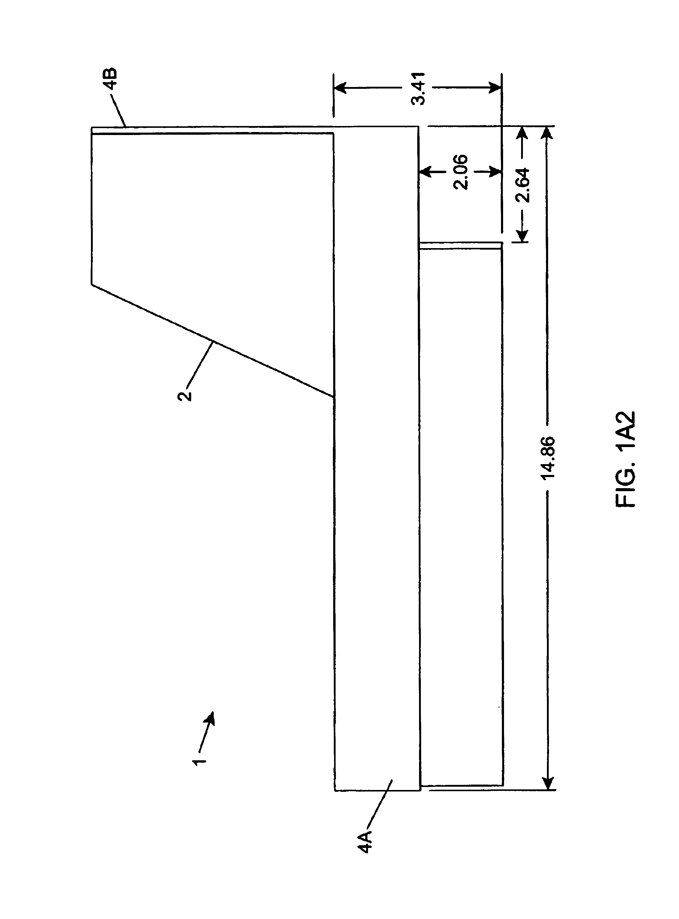
[0316]As shown in FIG. 1A, the bioptical holographic laser scanner of the first illustrative embodiment of the present invention 1 has a compact housing 2 having a first housing portion 4A, and a second housing portion 4B which projec...


PUM


Abstract

Disclosed is a bioptical laser scanning system that provides 360° of omnidirectional bar code symbol scanning coverage at a point of sale (POS) station. The system generates a 3-D omnidirectional laser scanning pattern between the horizontal and vertical scanning windows during system operation. The laser scanning pattern of the present invention comprises a complex of pairs of quasi-orthogonal laser scanning planes, each composed by a plurality of substantially-vertical laser scanning planes for reading bar code symbols having bar code elements (i.e. ladder-type bar code symbols) that are oriented substantially horizontal with respect to the horizontal scanning window, and a plurality of substantially-horizontal laser scanning planes for reading bar code symbols having bar code elements (i.e. picket-fence type bar code symbols) that are oriented substantially vertical with respect to the horizontal scanning window.

Description

RELATED CASES[0001]This is a Continuation of application Ser. No. 09 / 551,887 filed Apr. 18, 2000 now U.S. Pat. No. 6,758,402; which is a Continuation-in-Part of application Ser. No. 08 / 949,915 filed Oct. 14, 1997, now U.S. Pat. No. 6,158,659; application Ser. No. 08 / 726,522 filed Oct. 7, 1996, now U.S. Pat. No. 6,073,846; which is a Continuation of application Ser. No. 08 / 573,949 filed Dec. 18, 1995, now abandoned; which is a Continuation-in-Part of application Ser. No. 08 / 615,054 filed Mar. 12, 1996, now U.S. Pat. No. 6,286,760; Ser. No. 08 / 476,069 field Jun. 7, 1995, now U.S. Pat. No. 5,591,953; Ser. No. 08 / 561,479 filed Nov. 20, 1995, now U.S. Pat. No. 5,661,292; which is a Continuation of Ser. No. 08 / 293,695 filed Aug. 19, 1994, now U.S. Pat. No. 5,468,951; Ser. No. 08 / 293,493 filed Aug. 19, 1994, now U.S. Pat. No. 5,525,789; Ser. No. 08 / 475,376 filed Jun. 7, 1995, now U.S. Pat. No. 5,637,852; Ser. No. 08 / 439,224 filed May 11, 1995, now U.S. Pat. No. 5,627,359; and Ser. No. 08 / 2...

Claims


Application Information

Patent Timeline
Patent Type & Authority Patents(United States)
IPC IPC(8): G06K7/10G02B26/10G06K7/14G06K17/00G07G1/00
CPCG02B26/10G07G1/0054G06K7/10G06K7/10564G06K7/10584G06K7/10594G06K7/10603G06K7/10663G06K7/10673G06K7/10693G06K7/10702G06K7/10792G06K7/10801G06K7/10811G06K7/10851G06K7/10861G06K7/10871G06K7/10881G06K7/10891G06K7/109G06K7/14G06K17/0022G07F11/002G07G1/0045G02B26/106G06K2207/1012G06K2207/1013G06K2207/1016G06K2207/1017G06K2207/1018G07F9/002
Inventor CHECK, FRANKDICKSON, LEROYGROOT, JOHNGOOD, TIMOTHY
Owner METROLOGIC INSTR INC
Why Eureka
Try Eureka