Liquid crystal projector

a liquid crystal projector and cooling apparatus technology, which is applied in the field of cooling apparatus, can solve the problems of difficulty in maintenance and replacement of the lamp as a consumable part, and deterioration in cooling performan

Inactive Publication Date: 2006-01-31
HITACHI CONSUMER ELECTRONICS CORP
View PDF17 Cites 32 Cited by
  • Summary
  • Abstract
  • Description
  • Claims
  • Application Information

AI Technical Summary

Benefits of technology

[0008]Accordingly, a main object of the invention is to efficiently radiate the heat generated inside the liquid crystal projector, and in particular, generated in the light source lamp and the liquid crystal panel.
[0009]More precisely, a first object of the invention is to provide the liquid crystal projector capable of performing efficient cooling without causing the cooling liquid to boil, and of improving the maintenance property such as replacement of the lamp. Also, a second object is to provide the liquid crystal projector capable of avoiding an adverse effect on an outgoing beam from the liquid crystal projector due to flowing of the cooling liquid, and of implementing high reliability and the efficient cooling of the liquid crystal panel.
[0020]By adopting these configurations, it becomes possible to prevent the boiling of the cooling liquid and keep the high reliability of the projector because the cooling liquid does not directly contact the light source lamp of high temperature. It becomes also possible to simply detach the water-cooling jacket for receiving the heat from the lamp, and easily perform attaching and detaching work when replacing or maintaining the lamp. Further, it becomes possible to keep a sufficient heat transport amount to maintain the same cooling performance irrespective of an installation condition of the projector.
[0026]By adopting the configuration, it becomes possible to avoid the adverse effect on the outgoing beam from the liquid crystal projector due to the flow of the cooling liquid.

Problems solved by technology

However, all of the above-mentioned conventional techniques of cooling a light source lamp give no consideration to possibility of boiling of the cooling liquid used for the liquid cooling of the light source lamp of the liquid crystal projector or the like, rupture of a cooling liquid pipe, leak of the cooling liquid, difficulty in maintenance and replacement of the lamp as a consumable part, deterioration in cooling performance due to an installation location thereof, for example, in the case of being installed upside down (the deterioration in cooling performance is caused in the case of placing a liquid phase source on an upper side in a conventional heat pipe method), and so on.

Method used


Image

  • Liquid crystal projector
  • Liquid crystal projector
  • Liquid crystal projector

Examples


Embodiment Construction

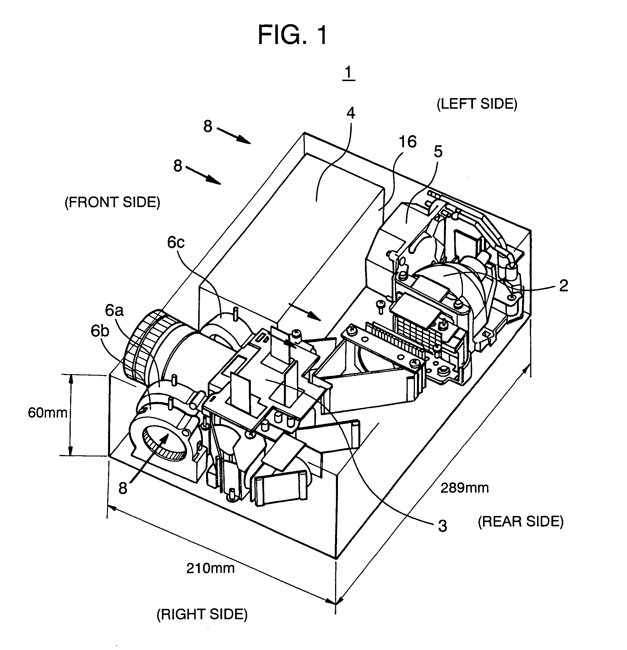
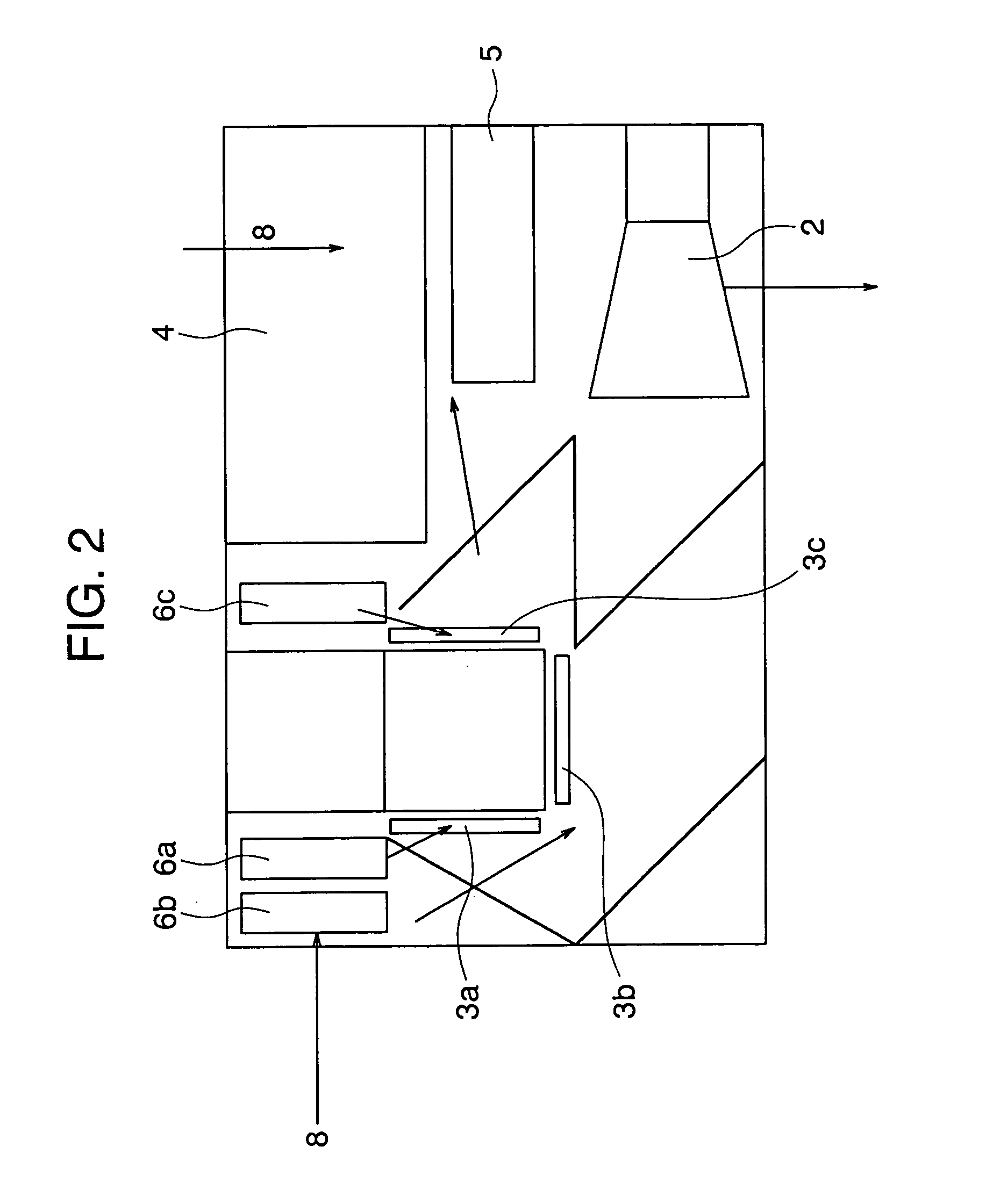
[0045]A liquid crystal projector according to the present invention will be described in detail below by referring to FIGS. 1 to 9. FIG. 1 is a perspective view showing a mounted arrangement of a liquid crystal projector having a power source, a fan, a liquid crystal panel, a light source lamp and so on, of an embodiment according to the present invention, and FIG. 2 is a plan view showing the mounted arrangement and air flow of the liquid crystal projector, of the embodiment according to the present invention. FIG. 3 is a perspective view showing the mounted arrangement of a cooling apparatus in the case of turning and opening a water-cooling jacket in the liquid crystal projector of the present embodiment.

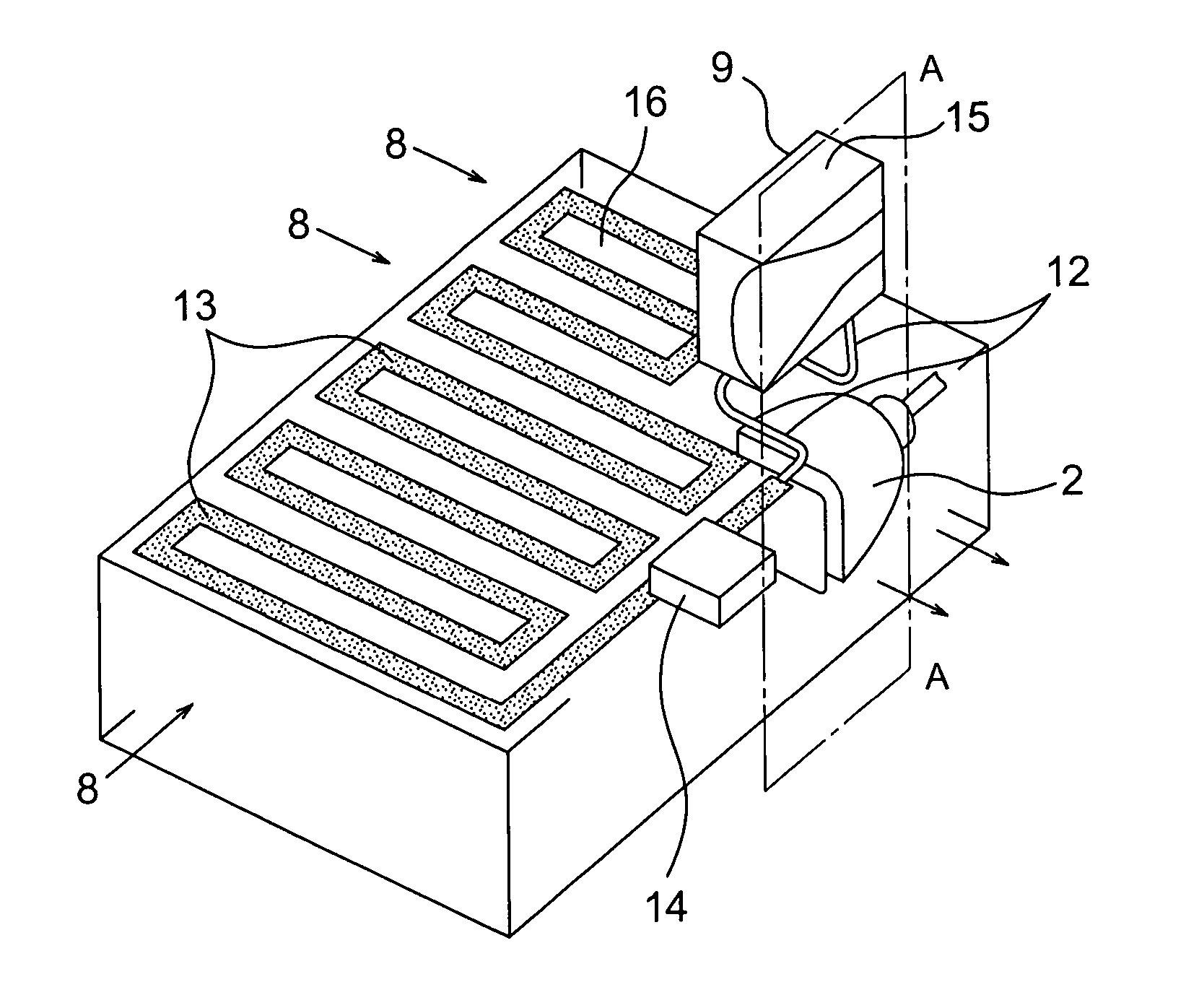
[0046]Also, FIG. 4 is a sectional view taken along the line A—A at the center of a lamp in FIG. 3 in a state of the water-cooling jacket being mounted, and FIG. 5 is a sectional view taken along the line B—B at a tip end of the lamp in FIG. 4. FIG. 6 is a sectional view taken alo...


PUM

PropertyMeasurementUnit
coloraaaaaaaaaa
electric poweraaaaaaaaaa
temperatureaaaaaaaaaa

Abstract

In order to perform high efficient cooling without boiling cooling liquid and to improve maintainability such as replacement of a lamp, the present invention provides a liquid crystal projector including a light source lamp, a liquid crystal panel, a power source, a fan for removing heat generated by the power source and the lamp, a water-cooling jacket provided on an inner surface of an external wall portion opposed to the lamp in the liquid crystal projector, a metal pipe arrangement for radiation which is placed in the external wall portion, and a pump for driving cooling liquid to flow in the water-cooling jacket so that the cooling liquid receiving the heat from the lamp circulates in a circulation path through the water-cooling jacket, the metal pipe arrangement, and the pump to emit the heat to the outside through the metal pipe arrangement.

Description

BACKGROUND OF THE INVENTION[0001]The present invention relates to a cooling apparatus for a general electronics device, and particularly to a cooling apparatus for a lamp and a liquid crystal panel of a liquid crystal projector.[0002]As a conventional technique of liquid cooling for a light source lamp of a liquid crystal projector or the like, it has been proposed to make cooled cooling fluid flow on a surface of a glass plate from a pipe arrangement provided on an upper portion of a light source so as to cool the light source, as shown in JP-A-8-273430, for example.[0003]Also, as another conventional technique, it has been proposed to connect one end of a heat pipe to a heat pipe provided in a lamp sealing portion and connect the other end to a pipe through which cooling liquid flows so as to cool the light source, as shown in JP-A-11-288045, for example.[0004]As a further conventional technique, it has been proposed to arrange a heat collecting member around a reflector of the li...

Claims


Application Information

Patent Timeline
Patent Type & Authority Patents(United States)
IPC IPC(8): G03B21/14G03B21/18G03B21/22G02F1/13G03B21/16H04N5/74
CPCG03B21/16H04N9/3141H04N5/7441
Inventor KONDO, YOSHIHIROSHIGYO, NARIAKINAKATANI, KATSUNORIMORITA, TATSUO
Owner HITACHI CONSUMER ELECTRONICS CORP
Why Eureka
Try Eureka