Sputtering target assemblies using resistance welding

a technology of resistance welding and target assemblies, which is applied in the direction of vacuum evaporation coating, coatings, manufacturing tools, etc., can solve the problems of generating very high mechanical stress in the metal body, affecting the performance of the sputtering target assembly, and adding weight to the bonding process

Active Publication Date: 2006-01-31
GLOBAL ADVANCED METALS USA
View PDF18 Cites 50 Cited by
  • Summary
  • Abstract
  • Description
  • Claims
  • Application Information

AI Technical Summary

Benefits of technology

[0005]A feature of the present invention is to provide a method of forming a sputtering target assembly which avoids the debonding issue by providing a fail-safe bond between the target and the backing plate.
[0007]A further feature of the present invention is to provide a method of forming a sputtering target assembly which prevents unintended sputtering of the backing plate.
[0012]Also, the present invention relates to a method of forming a sputtering target assembly which forms a gap between the assembled target and backing plate which reduces heat transfer between the target and the backing plate and increases the equilibrium temperature of the target during the sputtering process. The size of the gap between the assembled target and backing plate can be controlled by varying the relationship between the volume of the projections and the volume of the grooves.

Problems solved by technology

However, sputtering target assemblies bonded by methods at high temperatures can warp the assembly during use which affects performance of the sputtering target assembly, especially when a large difference exists between the coefficients of thermal expansion for the target and the backing plate.
Moreover, the differential thermal expansion between the target material and the backing plate material which occurs when bonding is accomplished at elevated temperatures by soldering, brazing, or diffusion bonding, generates very high levels of mechanical stress in the metal bodies.
The mechanical stress often causes deflection of the target assembly and can lead to bond failure so that the target separates from the backing plate during sputtering.
The bonding process also adds weight and creates the risk of having a target assembly debond while in use.
Additionally, the high temperatures associated with some conventional bonding methods can result in undesirable grain growth in the target metal.

Method used


Image

  • Sputtering target assemblies using resistance welding
  • Sputtering target assemblies using resistance welding
  • Sputtering target assemblies using resistance welding

Examples


Embodiment Construction

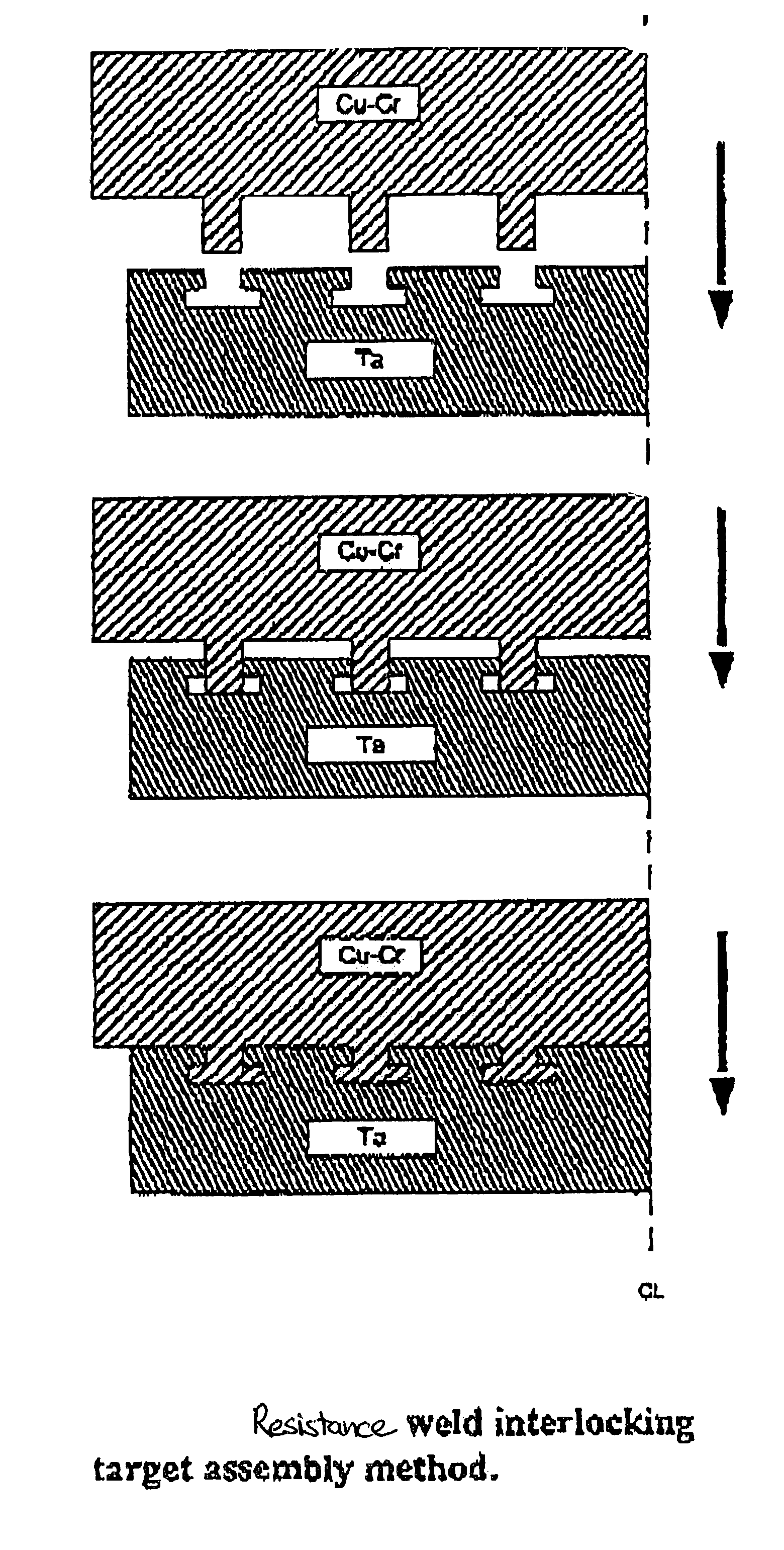
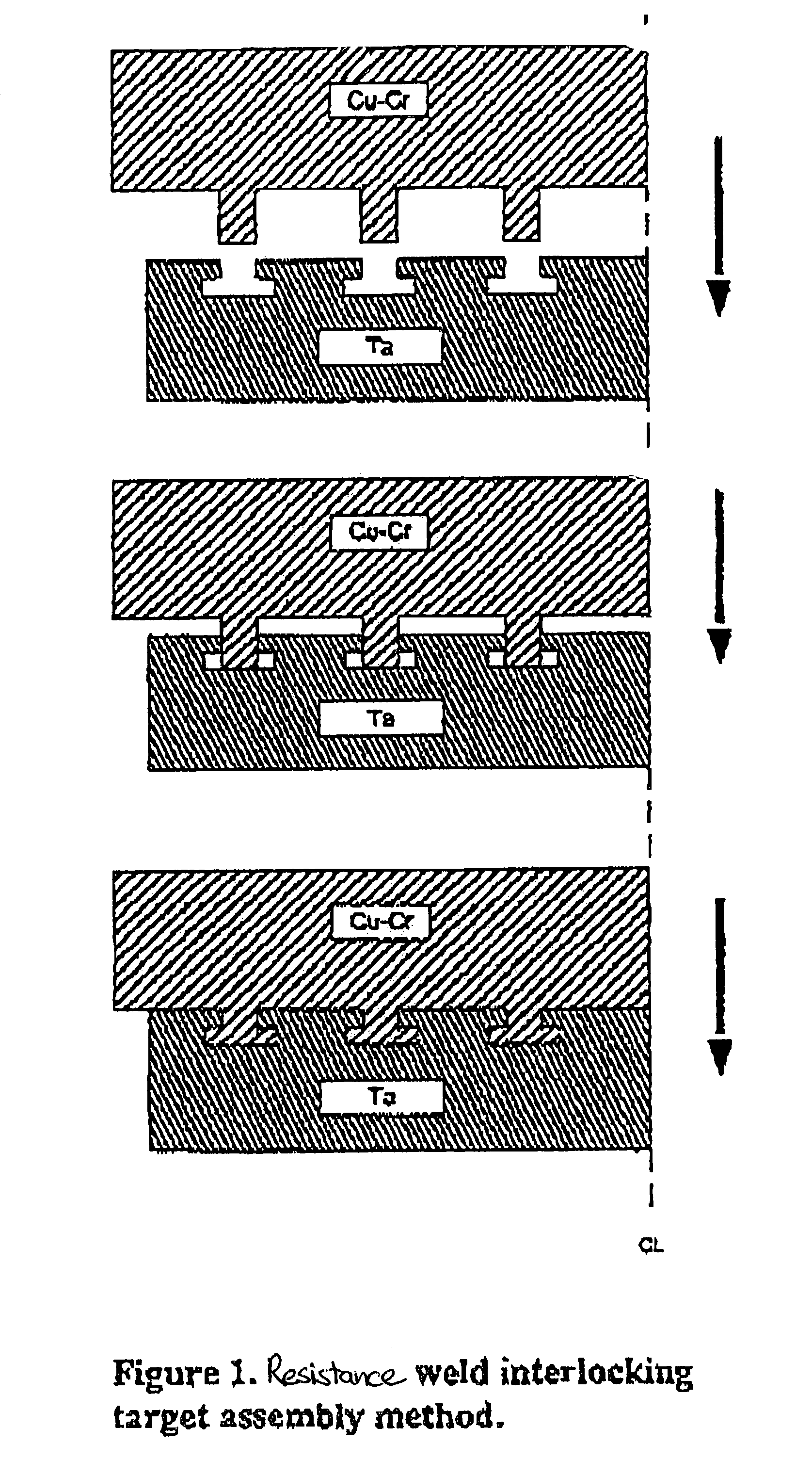
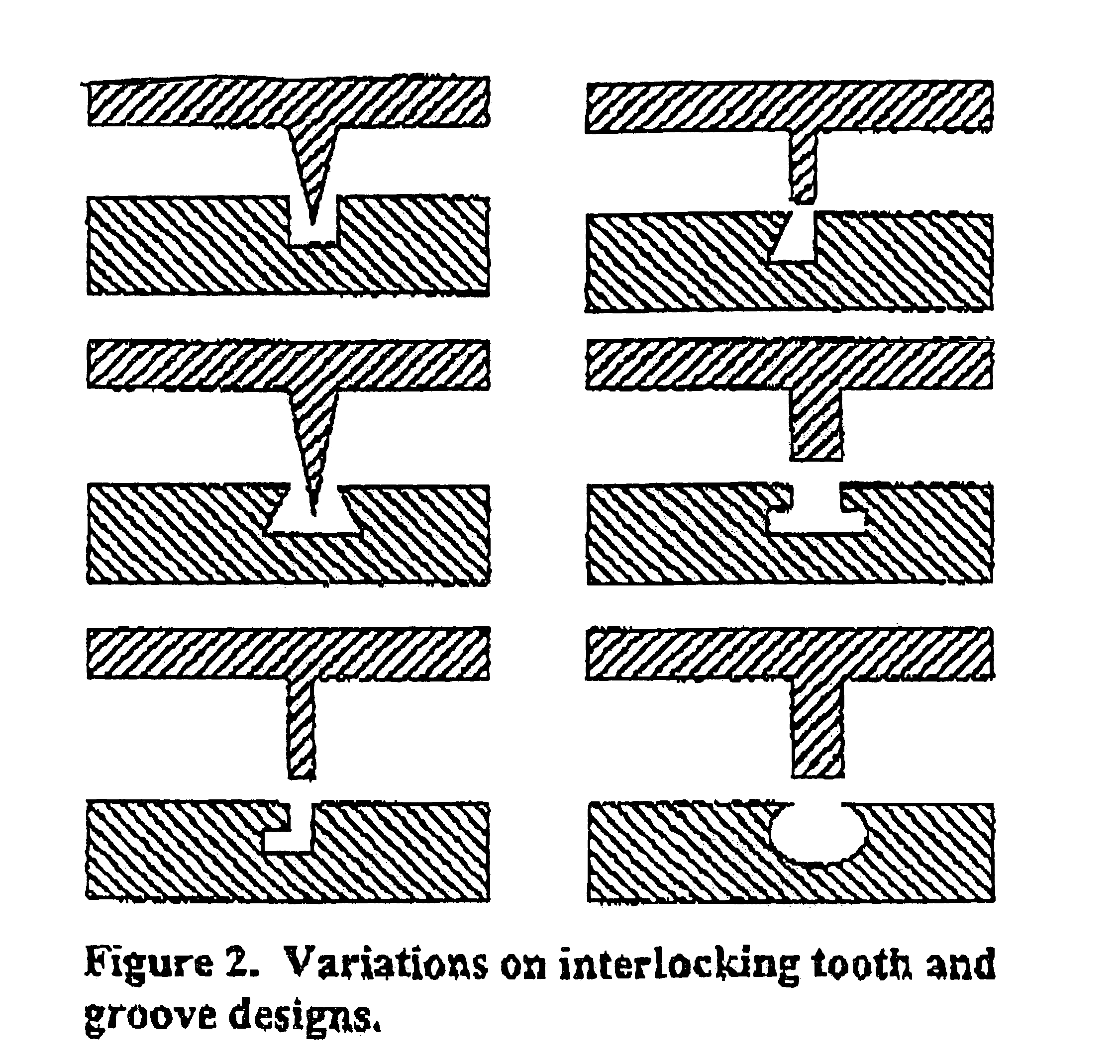
[0020]The present invention relates to a method of assembling a sputtering target assembly or other metal article by a bonding process that includes fixing a sputter target or other metal to a backing plate or other metal, preferably at a low temperature. The method includes contacting a portion of at least one projection on a bonding side of a first assembly member having a plurality of projections, against a portion of a groove on a bonding side of a second assembly member having a plurality of grooves; contacting a first electrode to one of the assembly members, and a second electrode to the other assembly member; conducting an electric current through the electrodes to cause resistance heating of the at least one projection and the groove; and partially deforming the at least one projection to a least partially fill the groove by applying a force between the projection and the groove, thereby forming at least a mechanical bond between the assembly members.

[0021]Preferably, the s...


PUM

PropertyMeasurementUnit
pressureaaaaaaaaaa
widthaaaaaaaaaa
pressureaaaaaaaaaa

Abstract

A method of forming a sputtering target assembly and other metal articles is described. Sputtering target assemblies and metal articles are also described. The method includes bonding a sputter target to a backing plate using resistance heating or welding to bond assembly members that respectively include mating projections and grooves formed in bonding surfaces thereof.

Description

BACKGROUND OF THE INVENTION[0001]The present invention relates to sputtering target assemblies and other metal articles, as well as methods of making the same. More particularly, the present invention relates to methods to bond various metals together to form bonded sputtering target assemblies and other bonded articles, preferably at a low temperature.[0002]In the sputter application field, typically a sputtering target assembly has a sputter target and a backing plate. For instance, a metal target or metal target blank (e.g., tantalum, titanium, aluminum, copper, cobalt, tungsten, etc.) is bonded onto a backing plate, such as a backing plate flange assembly such as copper, aluminum, or alloys thereof. To achieve good thermal and electrical contact between the target and the backing plate, these members are commonly attached to each other by means of soldering, brazing, diffusion bonding, clamping, and by epoxy cement and the like. However, sputtering target assemblies bonded by me...

Claims


Application Information

Patent Timeline
Patent Type & Authority Patents(United States)
IPC IPC(8): B23K11/14C23C14/34H01J37/34
CPCH01J37/3435C23C14/3407
Inventor KACHALOV, MIKHAIL Y.WICKERSHAM, JR., CHARLES E.
Owner GLOBAL ADVANCED METALS USA
Why Eureka
Try Eureka