Semiconductor memory device

a memory device and semiconductor technology, applied in the direction of solid-state devices, transistors, instruments, etc., can solve the problems of signal amount reduction, and achieve the effects of reducing array noise, improving refresh characteristic, and easy reading ou

Inactive Publication Date: 2006-01-31
LONGITUDE SEMICON S A R L
View PDF16 Cites 26 Cited by
  • Summary
  • Abstract
  • Description
  • Claims
  • Application Information

AI Technical Summary

Benefits of technology

[0016]Consequently, an object of the present invention is to provide a semiconductor memory device such as DRAM etc., which can realize high integration and ultra-high speed operation and largely reduce power consumption during a information maintaining period, by suppressing an increase in the area of a memory cell, obtaining ultra-high speed reading, and further achieving a long refresh period at the time of a self refresh.
[0028]As a result, the “L” data are certainly stored in either of the cells in the two cells / bit method. Accordingly, data on the side of the “L” has the readout speed higher than the “H” data, thereby allowing for ensuring the signal amount more stably. Additionally, in the operation of the folded bit-line method, the bit lines are arranged on the same array side, thereby allowing for canceling the substrate noises and the plate noises. Furthermore, since the wrap-around noises form the non-selected word line is also caused on the bit-line pair, the loss of the signal amount is prevented. Due to the advantages as described above, it is possible to obtain the stable bit-line signal on the “L” side. If it is directly read out, the data can be transmitted to the output buffer before the driving of the bit line.

Problems solved by technology

Also, since the one-intersection cell method of the one cell / bit must employ the open bit-line method, array noises become a problem, whereby a reduction in the signal amount is an object to be solved.

Method used


Image

  • Semiconductor memory device
  • Semiconductor memory device
  • Semiconductor memory device

Examples


Embodiment Construction

[0072]Hereinafter, an embodiment of the present invention will be described in detail with reference to the accompanying drawings. Note that components having the same functions are denoted by the same reference symbols throughout the drawings for describing the embodiment and the repetitive description thereof will be omitted.

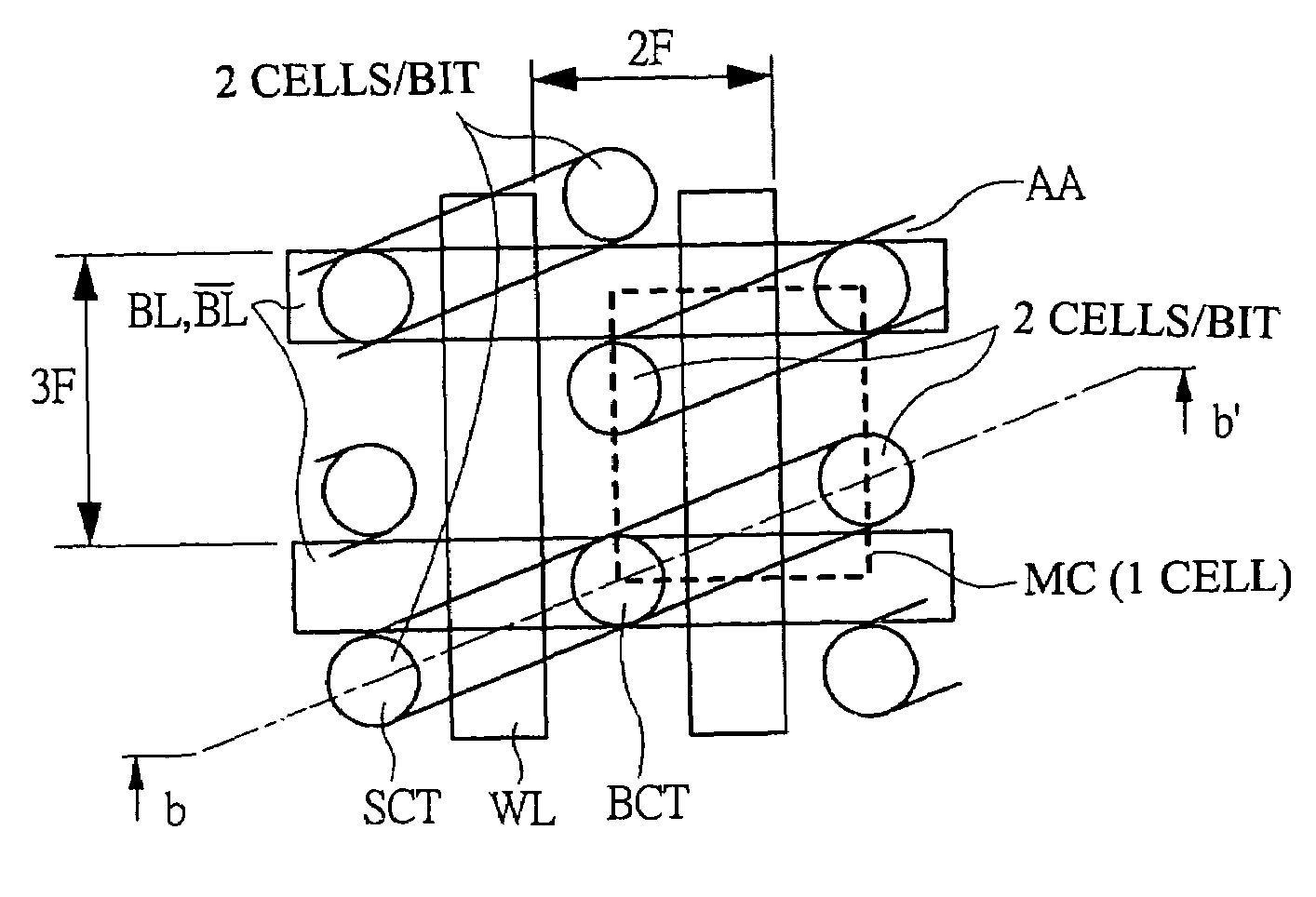
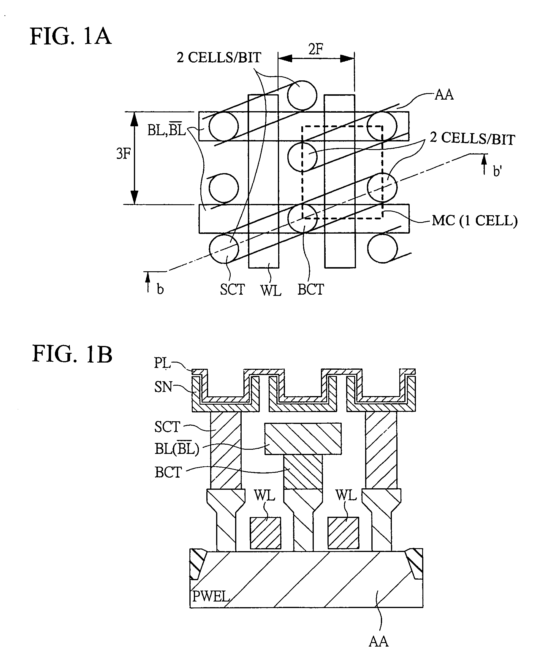
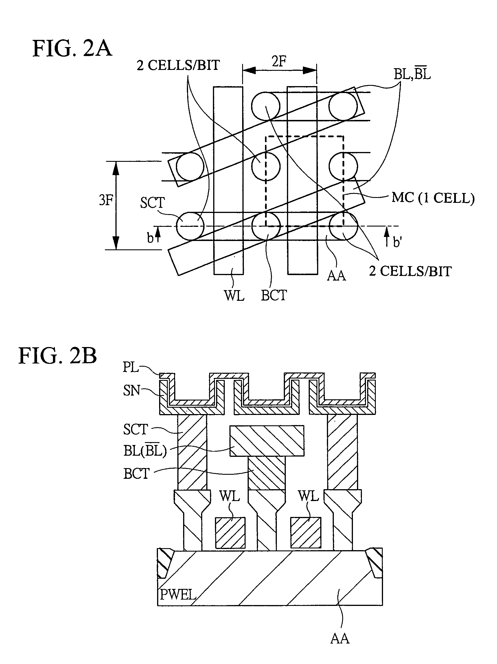
[0073]The semiconductor memory device according to an embodiment of the present invention is applied to, for example, a DRAM employing a one-intersection·two cells / bit method, and, though not particularly limited, is formed on one semiconductor substrate like single crystal silicon by a known semiconductor manufacturing technique. Particularly, the DRAM according to the embodiment is characterized by: 1. a twin cell structure employing a one-intersection 6F2 cell; 2. a direct sense+twin cell method; and 3. a substrate potential VSS+twin cell method, etc. and they will be sequentially described below.

[0074]1. Twin Cell Structure Employing One-intersection 6F2 C...


PUM


Abstract

A semiconductor memory device is provided which can achieve the high integration, ultra-high speed operation, and significant reduction of power consumption during the information holding time, by reducing the increase in the area of a memory cell and obtaining a period of the ultra-high speed readout time and ensuring a long refresh period at the time of the self refresh. A DRAM employing a one-intersection cell·two cells / bit method has a twin cell structure employing a one-intersection 6F2 cell, the structure in which: memory cells are arranged at positions corresponding to all of the intersections between a bit-line pair and a word line; and when a half pitch of the word line is defined as F, a pitch of each bit line of the bit-line pair is larger than 2F and smaller than 4F. Further, an active region in the silicon substrate, on which a source, channel and drain of the transistor of each memory cell are formed, is obliquely formed relative to the direction of the bit-line pair.

Description

CROSS-REFERENCE TO RELATED APPLICATIONS[0001]This is a Divisional of application Ser. No. 10 / 388,639, filed Mar. 17, 2003 now U.S. Pat. No. 6,828,612, the entire disclosure of which is hereby incorporated by reference.BACKGROUND OF THE INVENTION[0002]The present invention relates to s semiconductor memory device, and more particularly to a technique effectively applied to a semiconductor memory device such as a DRAM etc. adopting a connection method, which is called a two cells / bit method employing a so-called one-intersection cell.[0003]According to examinations by the inventors of the present invention, the following techniques are available for the DRAM as an example of the semiconductor memory device.[0004]For example, with respect to the DRAM, there are an open bit-line method and a folded bit-line method as methods of connecting a sense amplifier and a bit-line pair. The former open bit-line method is one in which two bit lines to be connected to one sense amplifier are separa...

Claims


Application Information

Patent Timeline
Patent Type & Authority Patents(United States)
IPC IPC(8): H01L27/108H01L29/94H01L31/119H01L29/76G11C11/401G11C7/18G11C11/403G11C11/405G11C11/406G11C11/4097H01L21/8242H01L27/02H01L31/0328
CPCG11C7/18G11C11/403G11C11/406G11C11/40615G11C11/4097H01L27/108H01L27/10885H01L27/10897H01L27/0207G11C2211/4013Y10S257/906H01L27/10814Y10S257/905H10B12/315H10B12/50H10B12/00H10B12/482
Inventor MIYATAKE, SHINICHIKAJIGAYA, KAZUHIKOMIYAZAWA, KAZUYUKISEKIGUCHI, TOMONORITAKEMURA, RIICHIROSAKATA, TAKESHI
Owner LONGITUDE SEMICON S A R L
Why Eureka
Try Eureka