System for the control and monitoring of sanitary appliances

a technology for electronic sanitary appliances and monitoring systems, applied in the direction of programme control, service pipe systems, water mains, etc., can solve the problem of inability to communicate with additional leads, and achieve the effect of low power consumption of battery-operated appliances

Inactive Publication Date: 2006-01-31
AQUA ROTTER
View PDF14 Cites 45 Cited by
  • Summary
  • Abstract
  • Description
  • Claims
  • Application Information

AI Technical Summary

Benefits of technology

[0011]The wireless control station should not only represent an interface for the transformation of signals transmitted in a line-bound manner into radio signals and vice versa, but should also communicate with the sanitary appliances connected to it in a wireless manner such that the power consumption of the battery-operated appliances is low if possible.

Problems solved by technology

However, the invention is also applicable to such appliances, to which an electrical distribution voltage is fed through a two conductor line, which means that additional leads are not available for data communication.

Method used


Image

  • System for the control and monitoring of sanitary appliances
  • System for the control and monitoring of sanitary appliances

Examples


Embodiment Construction

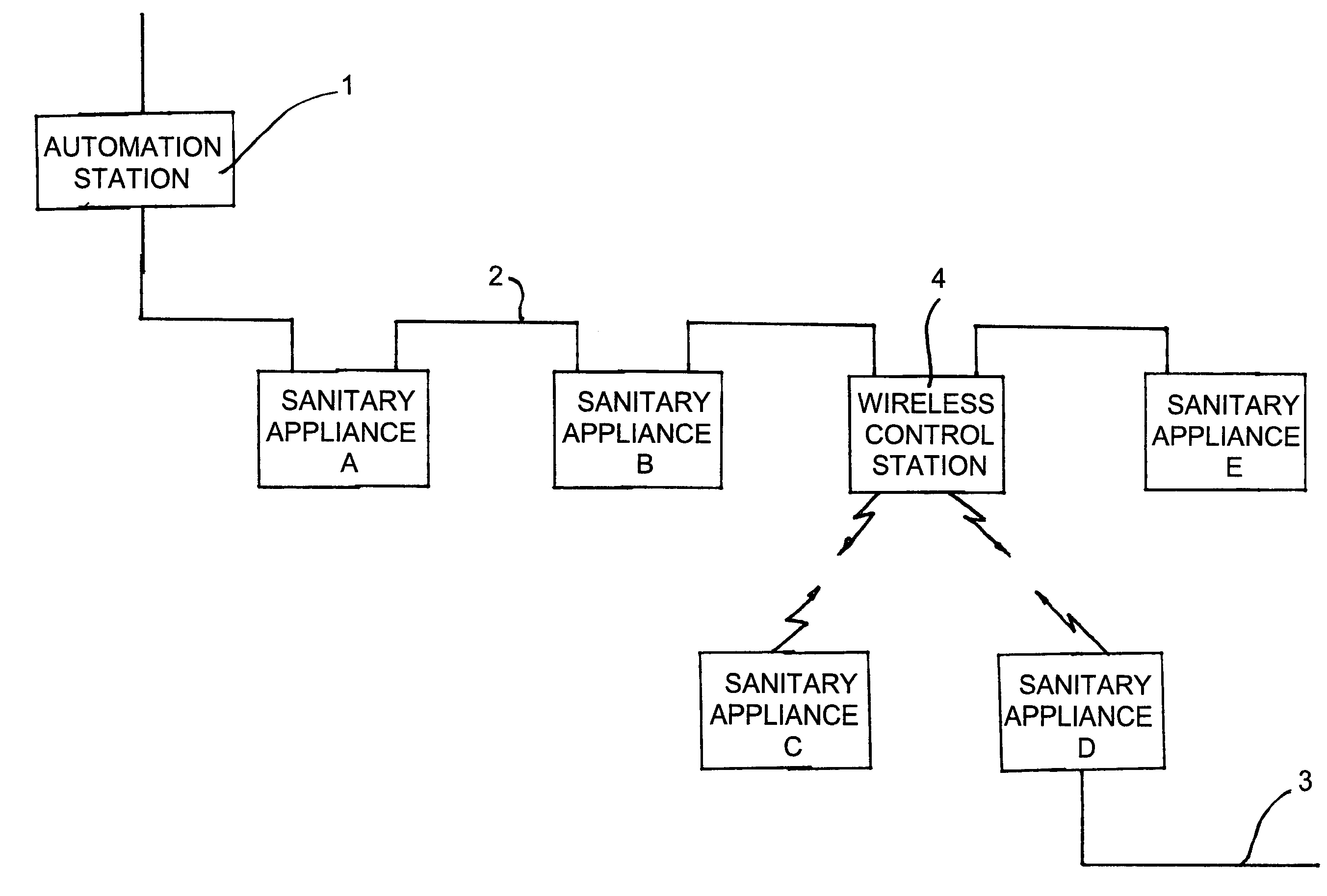
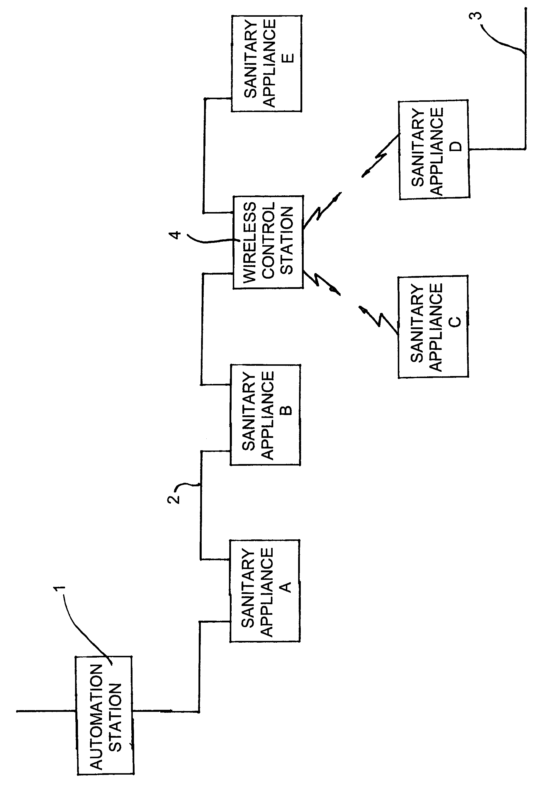
[0018]The sanitary appliances C and D are not directly connected to the field bus 2 because for economical or technical reasons, for example, it would be unsuitable to provide such a connection. The voltage supply of the sanitary appliance C is achieved by a battery whereas the appliance D is connected to a power supply network through a two conductor line 3.

[0019]In order to allow performing data communication between the automation station 1 and the sanitary appliances C and D, a wireless control station 4 is directly connected to the field bus 2 in the same way as the appliances A, B and E. The wireless control station 4 receives the control commands addressed to the appliances C and D from the automation station 1 through the field bus 2 and converts them into signals which can be transferred by wireless communication. The signals transmitted from the antenna of the wireless control station 4 are received by the antennas of the appliances C and D, and the appliance which the con...


PUM

PropertyMeasurementUnit
distanceaaaaaaaaaa
voltageaaaaaaaaaa
power consumptionaaaaaaaaaa

Abstract

A system for the control and monitoring of electronic sanitary appliances with a command level, an automation level and a field level. The automation level includes automation stations (1) which are each connected by a field bus (2) with several sanitary appliances (A, B, C, D, E). At least one radio station (4) is provided which communicates via a connected line with the appropriate automation station (1). The radio station (4) is in connection with at least one part (C, D) of the several sanitary appliances by means of a wireless data transmission path.

Description

BACKGROUND OF THE INVENTION[0001]This invention relates to a system for the control and monitoring of the electronic sanitary appliances with a command level, an automation level and a field level, and particularly to such systems in which the automation stations provided in the automation level are each connected to several sanitary appliances through a field bus.[0002]The applicant has developed a system for the control of sanitary installations in buildings which is known under the designation of AQUA 3000. This system is subdivided in a hierarchical manner into a management level or command level, an automation level and a field level.[0003]On the field level, all the water course operations required for the user are taking place by means of the appropriate sanitary appliances. The electronic sanitary appliances ready for bus are integrated into the data communication network for the control and monitoring through a four conductor cable, and are supplied moreover with the voltag...

Claims


Application Information

Patent Timeline
Patent Type & Authority Patents(United States)
IPC IPC(8): B01D21/30E03B7/04
CPCE03B7/04G05B2219/31395G05B2219/31394G05B2219/31162
Inventor SANDT, BURKHARDROSCHINSKY, CHRISTIANRENNAU, JOACHIM
Owner AQUA ROTTER
Why Eureka
Try Eureka