
Imaging apparatus

a technology of imaging apparatus and image quality, which is applied in the direction of exposure control, color signal processing circuit, instruments, etc., can solve the problems of signal creation, image quality deterioration, signal deterioration,

Inactive Publication Date: 2006-01-31
OLYMPUS CORP
View PDF12 Cites 11 Cited by
  • Summary
  • Abstract
  • Description
  • Claims
  • Application Information

AI Technical Summary

Benefits of technology

[0008]This invention has been made by taking the above condition into consideration and an object of this invention is to provide an imaging apparatus for obtaining high-quality images which is used for improving the conventional dark output correction technique and solving the above problem caused by output saturation of an imaging device or system when the dark output correction process is performed and which can be applied even in a case where the dark output levels of a large number of pixels in the entire portion of the image plane are enhanced, particularly, at the high temperature or at the time of long-time exposure.
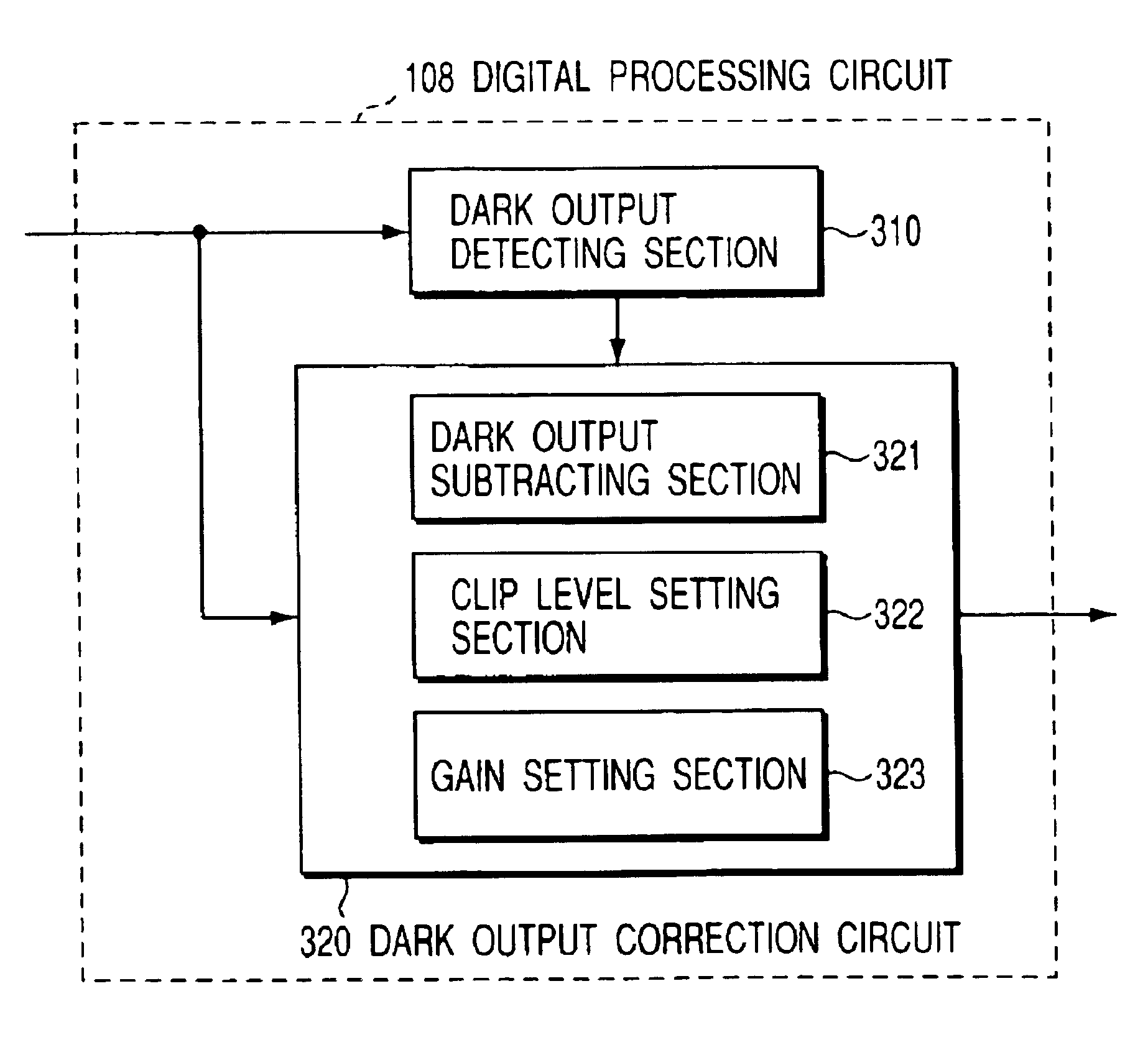
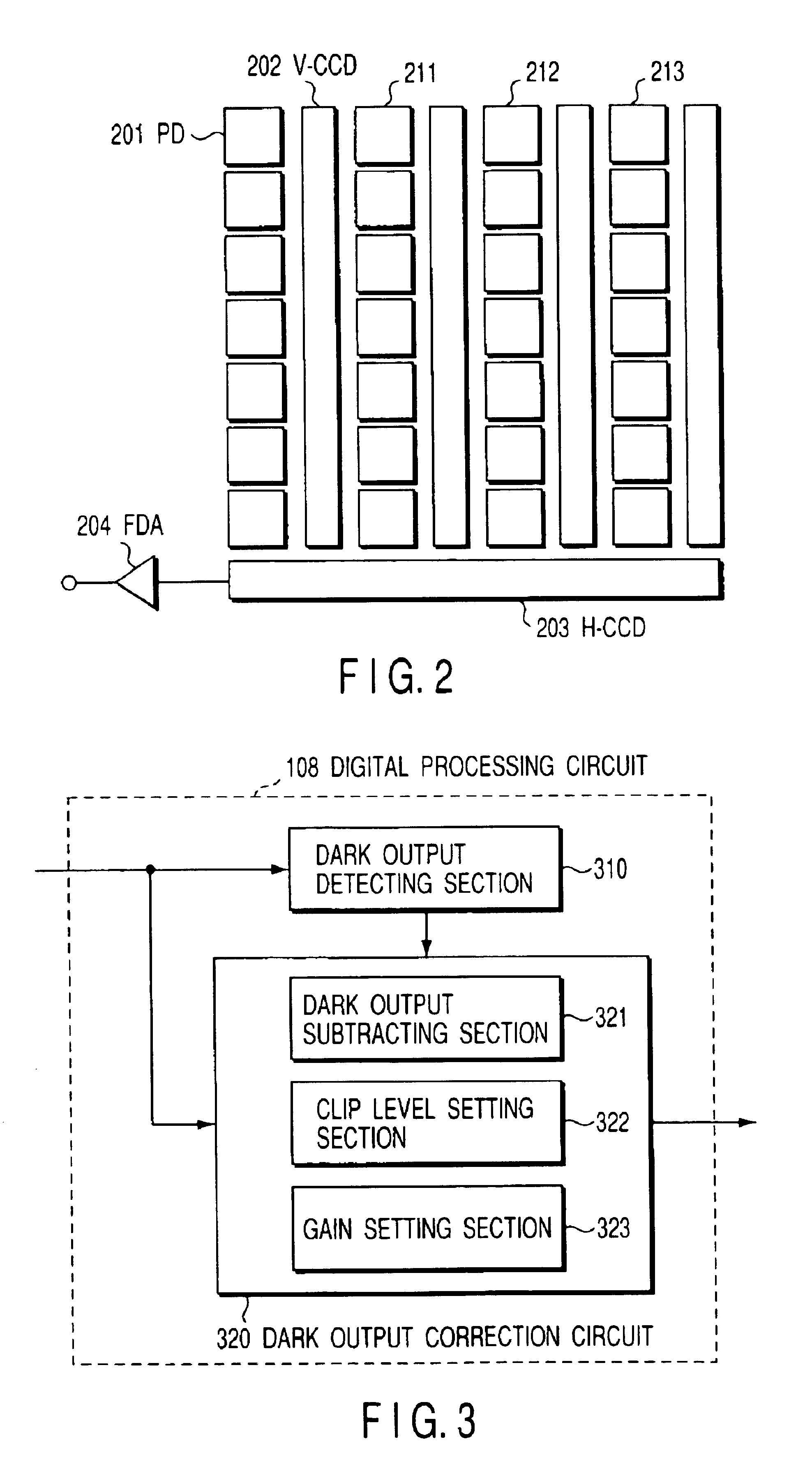
[0015]According to this invention with the above construction, an excellent effect that a false signal such as a black scar will not occur while the dark output correction is being made can be attained by setting the clip level for the subject signal component of a video signal according to the dark output level and setting the effective gain if required. Therefore, an imaging apparatus for obtaining high-quality images can be realized which can solve the problem caused by output saturation of the imaging device or system when the dark output correction process is effected and which can be applied even in a case where the dark output levels of a large number of pixels in the entire portion of the image plane are enhanced, particularly, at the high temperature or at the time of long-time exposure.

Problems solved by technology

In the imaging device, since a dark output due to a so-called dark current exists, there occurs a problem that the dark output is superposed on an image signal to deteriorate the image quality.
However, if the dark output correction process is simply effected by use of the conventional technique, a false signal is created by the correction process and deterioration of the image quality occurs when the dark output level is high since the output range of the imaging device used in the present electronic camera is limited.
More specifically, since the dark output correction process has the above problem, deterioration of the image quality due to the dark output is conventionally compensated for mainly by the pixel defect compensating technique.
However, in this type of pixel defect compensating technique, since the pixel information of the deteriorated pixel is made invalid and discarded, the resolution is locally lowered in principle.
When dark output levels of a large number of pixels are increased over the entire portion of the image plane, particularly, at the high temperature or at the time of long-time exposure, the number of substantially effective pixels is extremely reduced, and as a result, the image quality will be extremely deteriorated.

Method used


Image

  • Imaging apparatus
  • Imaging apparatus
  • Imaging apparatus

Examples


embodiment

[0027](Embodiment)

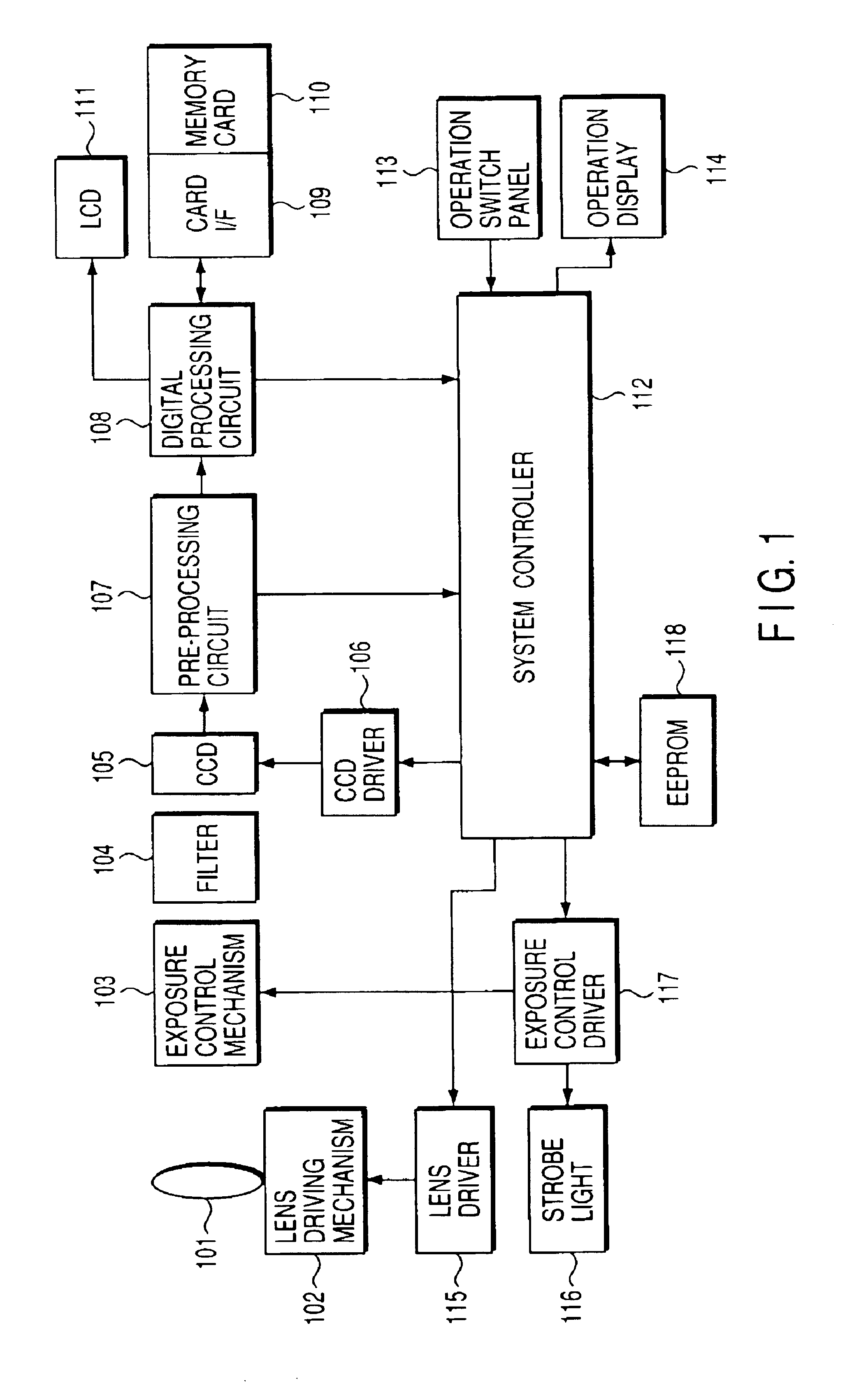
[0028]FIG. 1 is a block diagram showing the basic construction of an electronic still camera according to one embodiment of this invention. In this embodiment, a still camera used for imaging still pictures is explained, but a camera having a moving picture imaging function in addition to a still image picture imaging function can be used.

[0029]A reference numeral 101 in FIG. 1 denotes a photographing lens system having a plurality of lenses for guiding light rays from a subject into the camera. The lens system 101 is driven by a lens driving mechanism 102 so as to be focused on a subject. An exposure control mechanism 103 for controlling exposure includes a diaphragm and a diaphragm driving mechanism for driving the diaphragm and is provided to control the diaphragm so as to limit an incident light amount of the light ray which has passed through the lens system 101. Further, in the exposure control mechanism 103, a mechanical shutter is provided. The light ray ha...


PUM


Abstract

In an imaging apparatus for detecting a dark output level superposed on an imaging signal which is an output signal of an imaging device and correcting the imaging signal based on the detected dark output level, occurrence of a false signal caused by the dark output correction process is prevented and a substantial lowering in the effective imaging range is prevented by eliminating a dark output component from the imaging signal and setting a clip level and gain for a subject signal component according to the detected dark output level.

Description

CROSS-REFERENCE TO RELATED APPLICATIONS[0001]This application is based upon and claims the benefit of priority from the prior Japanese Patent Application No. 2000-28319, filed Feb. 4, 2000, the entire contents of which are incorporated herein by reference.BACKGROUND OF THE INVENTION[0002]This invention relates to an imaging apparatus having a function of correcting a dark output of an imaging device.[0003]Recently, in order to image and record mainly still pictures, electronic still cameras are developed. In video cameras for recording moving pictures, a still picture imaging / recording function is added. When photographing still pictures by use of the above cameras, the so-called long-time exposure technique in which the exposure time is elongated by making long the charge storage time of the imaging device is used. In the long-time exposure technique, the photographing can be attained without using an auxiliary light source such as a strobe light in a low illumination environment.[...

Claims


Application Information

Patent Timeline
Patent Type & Authority Patents(United States)
IPC IPC(8): H04N9/64H04N23/76
CPCH04N5/2176H04N5/243H04N5/2352H04N2101/00H04N25/63H04N23/72H04N23/76
Inventor YOSHIDA, HIDEAKI
Owner OLYMPUS CORP
Learn More