Image position detecting method
a detection method and image technology, applied in the field of detection methods, to achieve the effect of precise color registration and good color image formation quality
- Summary
- Abstract
- Description
- Claims
- Application Information
AI Technical Summary
Benefits of technology
Problems solved by technology
Method used
Image

Examples
first embodiment
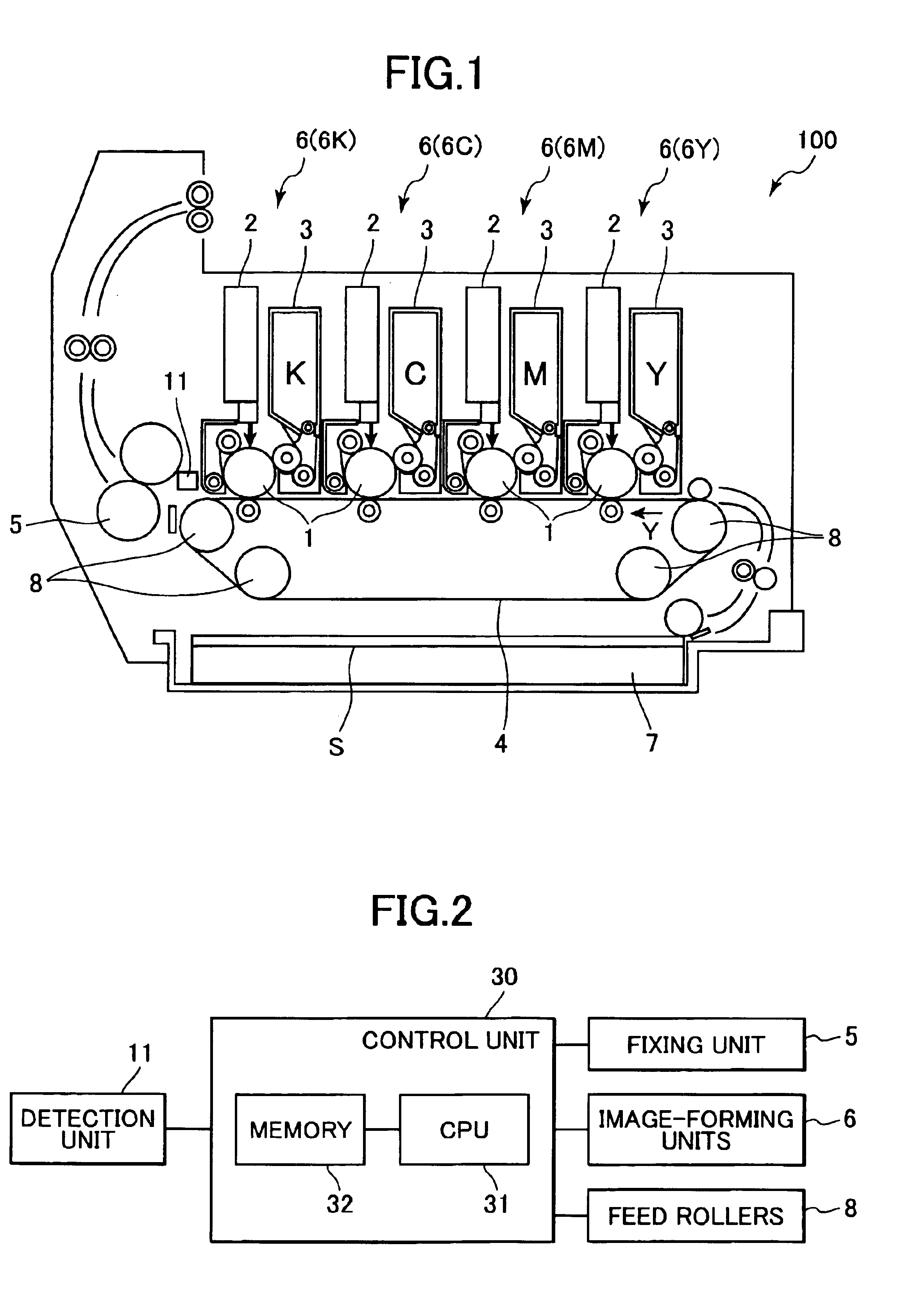
[0037]An image position detecting method and an electrophotographic recording device according to the present invention will be described with reference to FIGS. 1 to 6. In this embodiment, a tandem color recording device 100 shown in FIG. 1 is taken as an example of the electrophotographic recording device of the present invention.
[0038]As shown in FIG. 1, the tandem color recording device 100 includes a sheet-supply unit 7, a transfer belt 4, a plurality of feed rollers 8, a plurality of image-forming units 6 (6K, 6C, 6M, 6Y), and a fixing unit 5.
[0039]The sheet supply unit 7 stores a stack of recording sheets S and supplies the recording sheets S one at a time onto the transfer belt 4. The transfer belt 4 is wound around the feed rollers 8 and rotates in a sub-scanning direction Y as the rollers 8 are driven to rotate, thereby transporting the recording sheet S in the sub-scanning direction Y.
[0040]The image-forming units 6 are arranged in the sub-scanning direction Y. Each of th...
second embodiment
[0069]Next, a detecting method according to the present invention will be described with reference to FIGS. 8 and 9. In this embodiment, patches 120 shown in FIG. 8 (only one patch 20 is shown in FIG. 8) are used. The patches 120 are wider than the light-detecting range of the sensor 21a, 21b, 21c, 21d in the sub-scanning direction Y. By forming each patch 120 wider than the width of the sensor 21a, 21b, 21c, 21d, a voltage of a detection signal from each sensor 21a, 21b, 21c, 21d levels off at a maximum value E as shown in FIGS. 9(a). Note that the detection signal reaches the maximum value E when the entire sensor 21a, 21b, 21c, 21d confronts the patch 120, and the timing at which the detection signal reaches a maximum value E has been known as a timing TA.
[0070]When detection starts, the waveform C1 of the detection signal from the sensor 21a is sequentially stored into the memory 32, and a voltage value at the timing TA is detected and stored into the memory 32 as the maximum va...
third embodiment
[0076]Next, a detecting method according to the present invention will be described with reference to FIGS. 10 and 11.
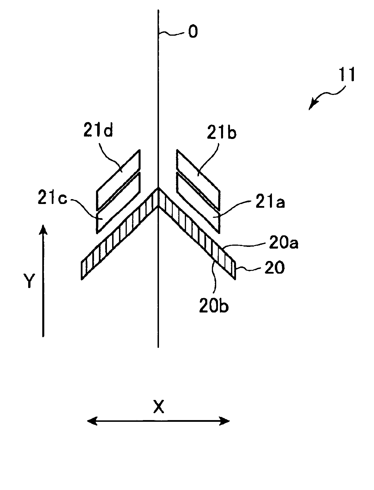
[0077]FIG. 10 shows the positional relationship of patch 220 and the sensors 21a-21d. The patch 220 is formed wider in the sub-scanning direction Y than the width of each sensor 21a, 21b, 21c, 21d. Further, a leading edge 220a and a tailing edge 220b of the patch 220 are at a slightly different angle from the sensors 21a-21d.
[0078]As shown in FIG. 11(a), by slightly offsetting the angles of the patch 220 and the sensors 21a, 21b, the sensor 21b starts outputting a detection signal at timing TB before a detection signal from the sensor 21a a reaches a maximum value E at timing TA.
[0079]In this embodiment, the maximum value of the waveform C1 and C2 is previously stored in the memory 32 for the following reason. That is, as mentioned above, the sensor 21b starts outputting the detection signal before the detection signal from the sensor 21a reaches the maximum value E...
PUM
 Abstract
Description
Claims
Application Information
 - R&D
- Intellectual Property
- Life Sciences
- Materials
- Tech Scout
- Unparalleled Data Quality
- Higher Quality Content
- 60% Fewer Hallucinations
Browse by: Latest US Patents, China's latest patents, Technical Efficacy Thesaurus, Application Domain, Technology Topic, Popular Technical Reports.
© 2025 PatSnap. All rights reserved.Legal|Privacy policy|Modern Slavery Act Transparency Statement|Sitemap|About US| Contact US: help@patsnap.com