Radio frequency signal attenuation circuitry and gain controlling unit

a technology of attenuation circuit and gain control, which is applied in the direction of radio transmission, transmission monitoring, electrical equipment, etc., can solve the problems of receiving radio signal, radio terminal may not be able to properly process the signal, and received radio signal may appear or sound distorted to a user

Inactive Publication Date: 2006-01-31
LG ERICSSON
View PDF4 Cites 6 Cited by
  • Summary
  • Abstract
  • Description
  • Claims
  • Application Information

AI Technical Summary

Benefits of technology

[0007]Accordingly, the object of the present invention is to avoid distortion at a radio terminal due to a received RF signal which has a voltage strength that is too high. Particularly, the present invention relates to an apparatus including radio frequency signal attenuation circuitry, radio frequency signal processing circuitry, intermediate frequency processing circuitry and a gain controlling unit. The gain controlling unit is configured to output a control signal to the radio frequency signal attenuation circuitry and intermediate frequency processing circuitry.
[0008]The present invention utilizes the radio frequency attenuation circuitry to lower the strength of a received radio frequency signal which is too high. This is advantageous, as once a relatively high radio frequency signal is attenuated, the radio frequency signal processing circuitry and intermediate frequency processing circuitry can adequately process the received signal without producing distortion. In other words, prior to a relatively high voltage radio frequency signal being processed by a radio terminal, the radio frequency signal is selectively reduced to a reasonable level. Control of the radio frequency signal attenuation circuitry is accomplished by the gain controlling unit.

Problems solved by technology

This can become problematic in radio terminals when the strength of a received radio frequency signal is too high.
When the strength of such a radio frequency signal is too high, the radio terminal may not be able to process the signal properly.
In these instances, a received radio signal may appear or sound distorted to a user.
Particularly, when a radio terminal receives a high power radio frequency (RF) signal, the components of the radio terminal may become saturated and cause the undesirable distortion.
Another disadvantage of a radio terminal receiving a high voltage signal is that the radio terminal may become disconnected, which is annoying to the user.

Method used


Image

  • Radio frequency signal attenuation circuitry and gain controlling unit
  • Radio frequency signal attenuation circuitry and gain controlling unit
  • Radio frequency signal attenuation circuitry and gain controlling unit

Examples


Embodiment Construction

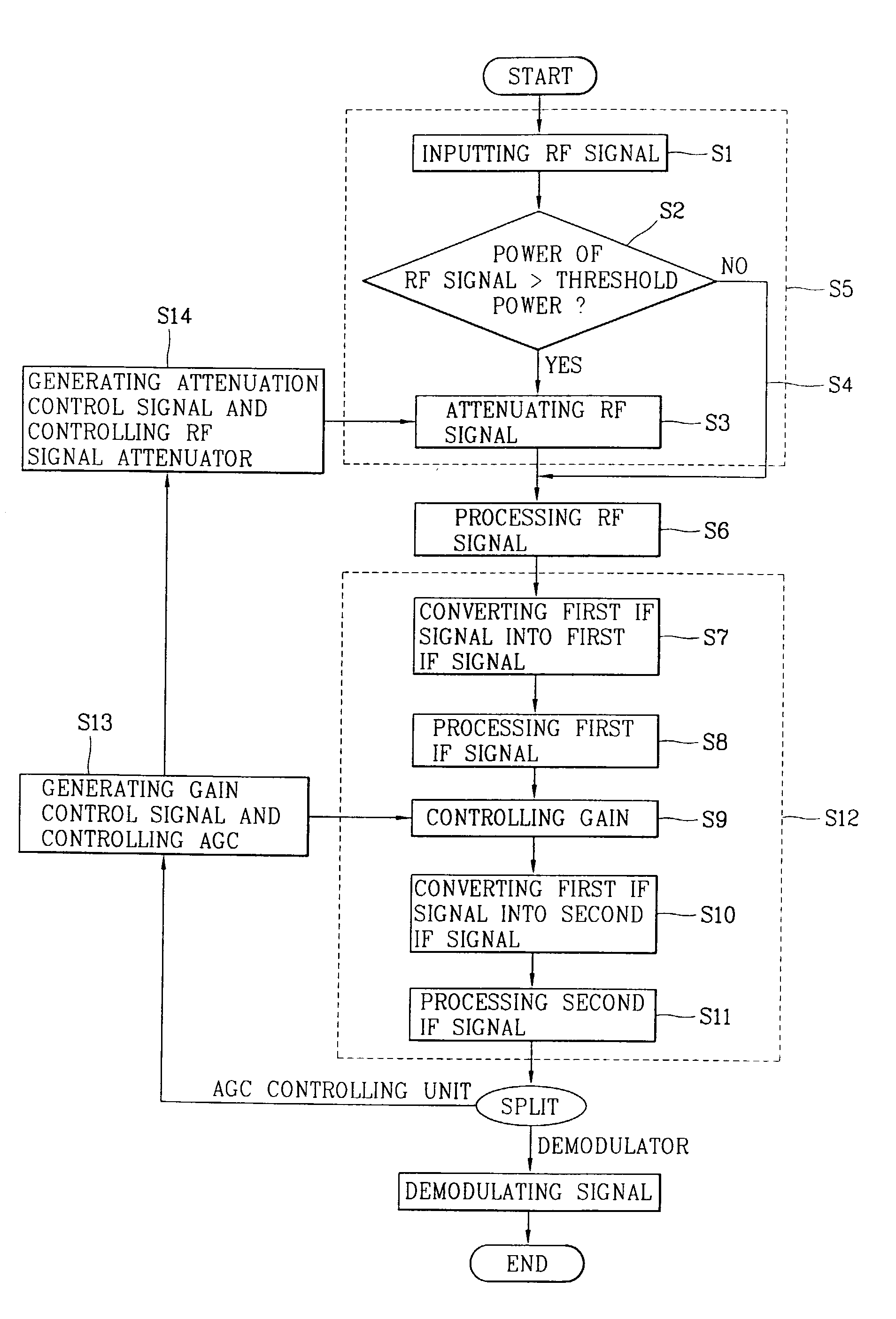
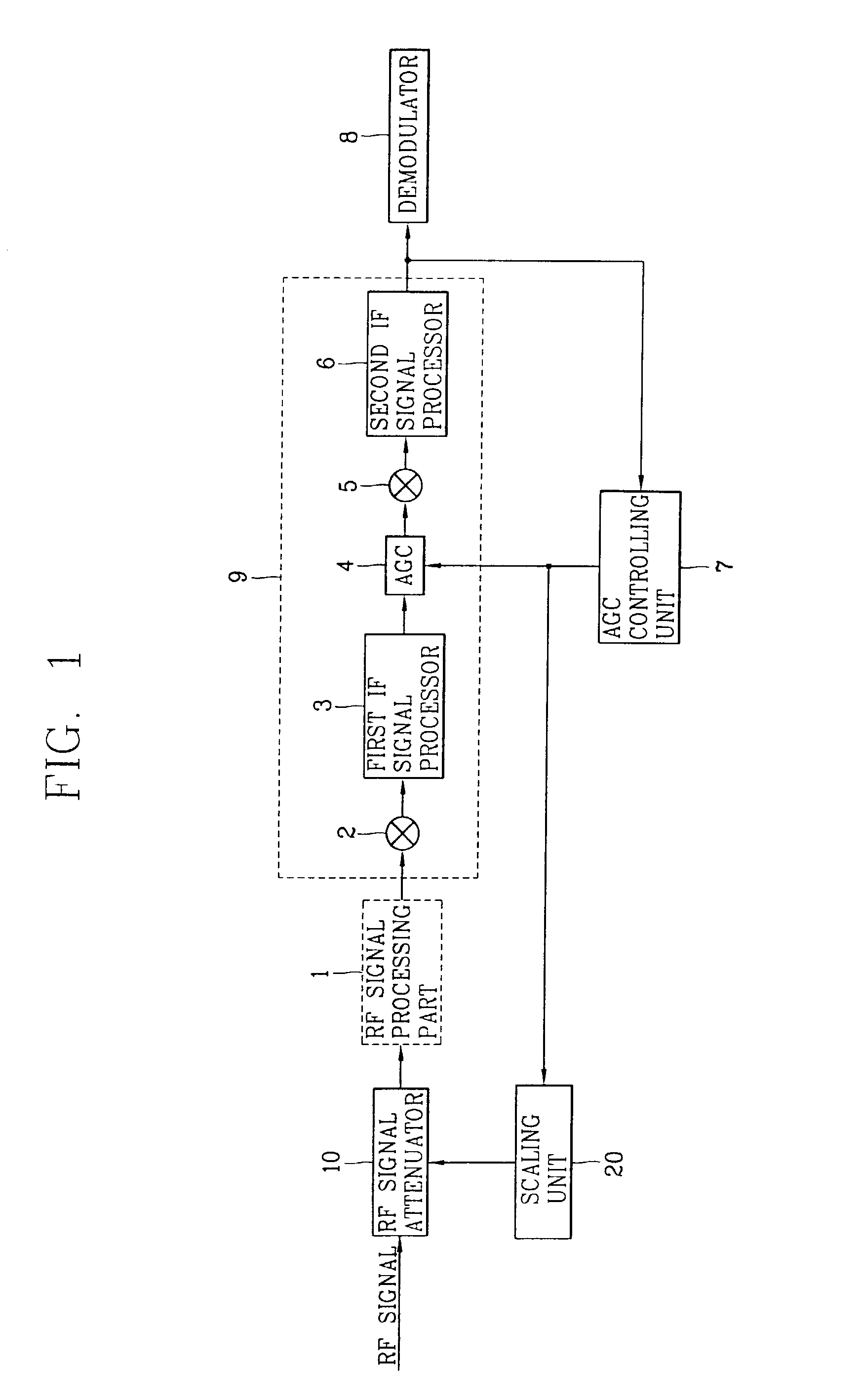
[0017]FIG. 1 is a block diagram of an exemplary automatic gain control apparatus. The apparatus includes a Radio Frequency (RF) signal attenuator 10, a RF signal processing part or processor 1, an Intermediate Frequency (IF) processing part or processor 9, demodulator 8, automatic gain control (AGC) controlling unit or controller 7, and scaling unit or scaler 20. The RF signal processing part 1 is configured to receive and process RF signals output from RF signal attenuator 10. The IF signal processing part 9 is configured to convert the processed RF signal output from RF signal processing part 1 to generate an IF signal. Automatic Gain Controller (AGC) controlling unit 7 is configured to generate a gain control signal. The gain control signal is in accordance with a difference between a voltage level of an output signal of the IF signal processing part 9 and a reference voltage level. Scaling unit 20 is configured to scale the gain control signal output from AGC controlling unit 7 ...


PUM


Abstract

The present invention avoids distortion in a radio frequency device due to a received RF signal which has a voltage strength that is too high. The invention comprises a radio frequency signal attenutation circuitry, a radio frequency signal processing circuitry, intermediate frequency processing circuitry, and a gain controlling unit. The gain controlling unit is configured to output a control signal to the radio frequency signal attenuation circuitry and intermediate frequency processing circuitry. The radio frequency signal attenuation circuitry is configured to attenuate a radio frequency signal prior to being processed by radio frequency processing circuitry and intermediate frequency processing circuitry. Accordingly, saturation in the radio frequency signal processing circuitry and intermediate frequency processing circuitry is avoided.

Description

BACKGROUND OF THE INVENTION[0001]1. Field of the Invention[0002]The present invention relates to a gain controlling unit configured to output a control signal to radio frequency signal attenuation circuitry and intermediate frequency processing circuitry.[0003]2. Background of the Related Art[0004]Mobile radio communications systems are used in everyday life. Garage door openers, remote controllers for home entertainment equipment, cordless telephones, hand held walkie-talkies, pagers, and cellular telephones are all examples of mobile radio communications systems. The term mobile has historically been used to classify any radio terminal that can be moved during operation. More recently, the term mobile is used to describe a radio terminal that is attached to a high speed mobile platform (e.g., a cellular phone in a fast moving vehicle) whereas the term portable means a radio terminal that can be hand-held and used by someone at a walking speed (e.g., a walkie-talkie or cordless tel...

Claims


Application Information

Patent Timeline
Patent Type & Authority Patents(United States)
IPC IPC(8): H04B17/02H04B1/10H03G3/30H04B17/40
CPCH03G3/3068H04B1/10
Inventor KWUN, SOON-IK
Owner LG ERICSSON
Why Eureka
Try Eureka