Starting apparatus

a technology of starting apparatus and starting gear, which is applied in the direction of engine starters, machines/engines, couplings, etc., can solve the problems of large physical configuration of the motor, unconstant reaction force applied to the internal gear, and unpleasant sound likely to be caused in the engine start-up process, etc., and achieves simple structure and reduce vibration

Inactive Publication Date: 2006-02-07
DENSO CORP
View PDF13 Cites 18 Cited by
  • Summary
  • Abstract
  • Description
  • Claims
  • Application Information

AI Technical Summary

Benefits of technology

[0025]The reaction force is gradually elastically received by the unmovable locking portion. Therefore, it is less likely that shock load will be applied to respective portions and unpleasant sound will be caused by direct contact of locking members. Further, the shock absorbing member also works as a vibration isolating member and therefore, can absorb vibration and sound generated at the reduction gear or a surrounding thereof. In this way, the reduction gear can reduce vibration, unpleasant sound generated in operating the starting apparatus although the reduction gear is provided with a comparatively simple structure.

Problems solved by technology

Therefore, when the engine is cranked directly by the motor, the physical configuration of the motor naturally becomes large.
The motor of the starter cannot well follow such a load variation or the like and therefore, impact load is applied between the internal gear and a rotation restricting portion thereof.
Further, the reaction force applied to the internal gear is not constant.
As a result, unpleasant sound is likely to be caused in starting the engine due to vibration or the like of the internal gear by simply constraining the internal gear.
When the internal gear is rigidly restricted here, it is required to reinforce the internal gear or the restricting portion to be able to withstand the shock load, which hampers light-weighted compact formation of the starter.
However, an outer diameter of a reduction gear is increased thereby and compact formation of a starter is not achieved.
However, the projection of the internal gear is not held elastically by the shock absorbing member from the start.
Therefore, shock load is not necessarily alleviated sufficiently from start of operation thereof.
Therefore, the structure of the starting apparatus is complicated.
Therefore, compression operability of the shock absorbing member is poor and the shock absorbing member is likely to easily wear.
In addition, the internal gear is not provided with a detent and therefore, the internal gear continues rotating little by little while the exerted reaction force is large.
As a result, efficiency of transmitting driving force of the motor is likely to be lessened.

Method used


Image

  • Starting apparatus
  • Starting apparatus
  • Starting apparatus

Examples


first embodiment

[0040]the present invention will be described hereinafter with reference to FIGS. 1 through 3.

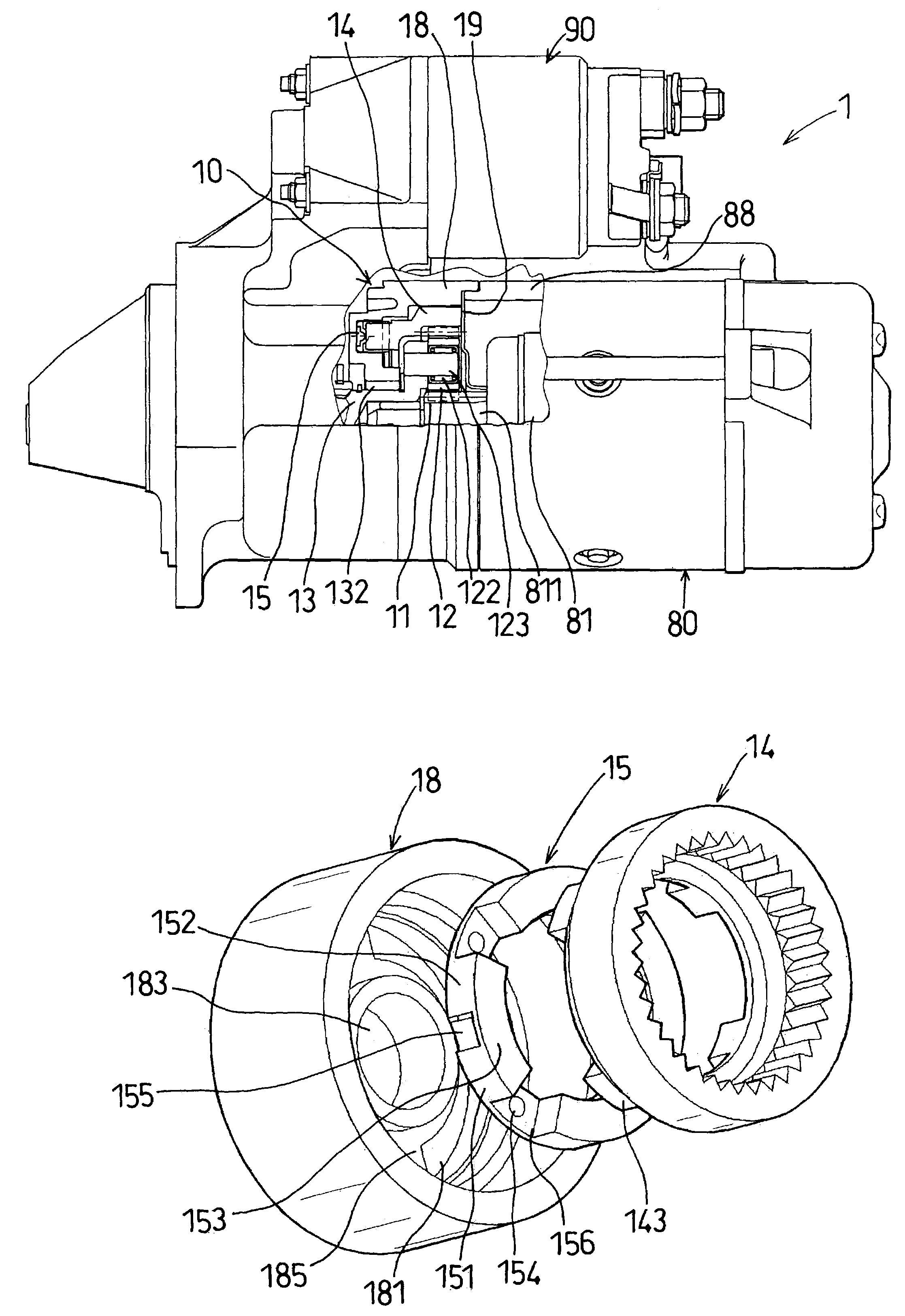
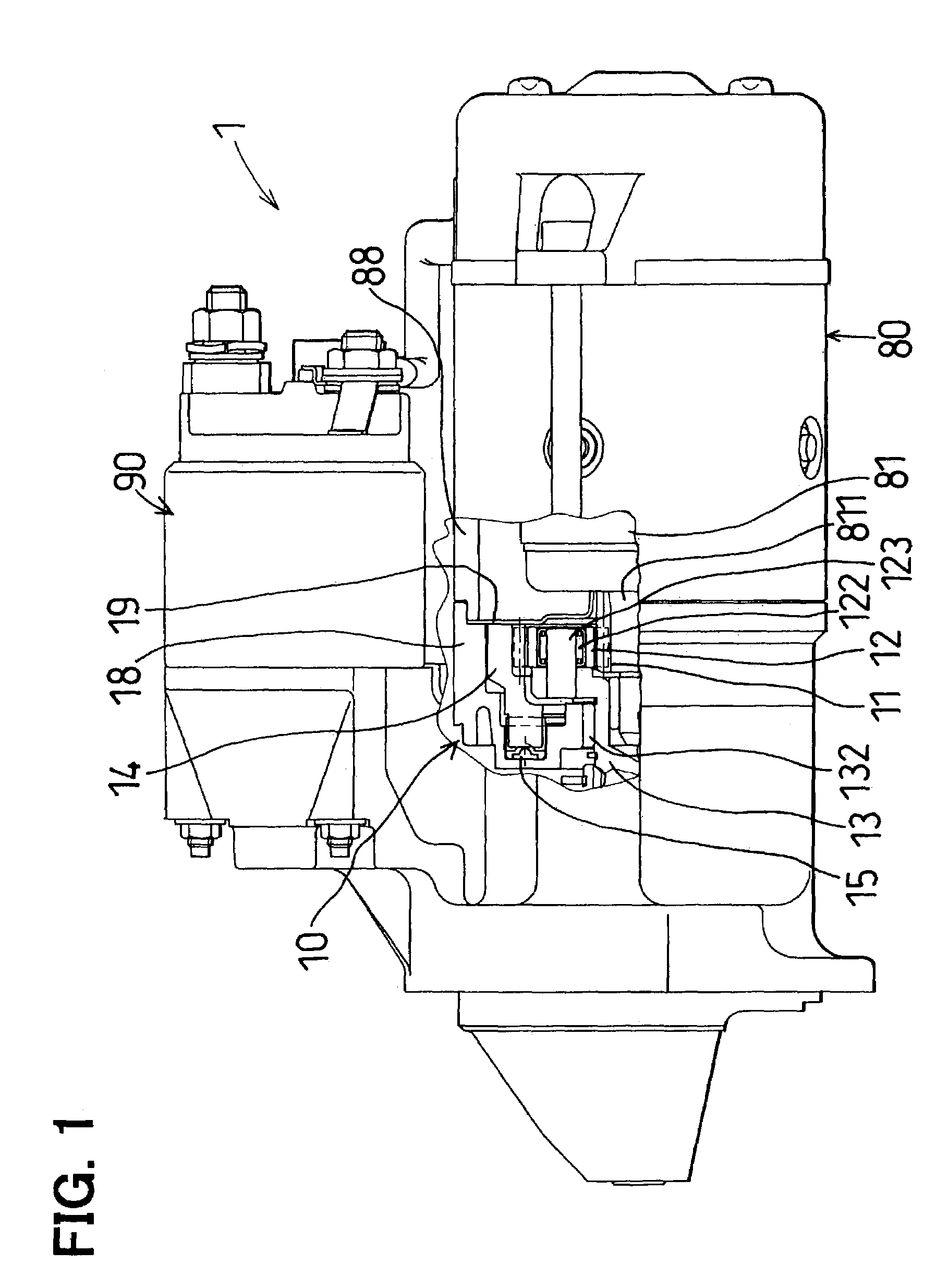
[0041]FIG. 1 shows a gear-type starter (hereinafter, simply referred to as a starter) 1. The starter 1 mainly includes a reduction gear 10, a motor 80 and a magnet switch 90. Although not illustrated in details, an output of the motor 80 is transmitted to an output shaft that is formed with a helical spline on its outer peripheral face via the reduction gear 10.

[0042]An overrunning clutch (one way clutch) and a pinion gear are arranged on the helical spline. (See, FIG. 7) In starting, the overrunning clutch and the pinion gear are pushed in an axially forward direction (to a left side of FIG. 1) by lever operation of the magnet switch 90. Further, the pinion gear is temporarily brought in mesh with a ring gear attached to a crankshaft of the engine to thereby crank the engine. When the engine has been started, the pinion gear of the starter 1 is idly rotated by the overrunning clutch to the...

second embodiment

[0058]Next, the second embodiment will be described with reference to FIG. 4.

[0059]In the second embodiment, a shock absorbing member 25 has a shape different from the shape of the shock absorbing member 15 of the first embodiment. Shock load applied to the internal gear 14 is absorbed by four independent shock absorbing members 25 each having the same shape.

[0060]Each of the shock absorbing member 25 includes a first elastic block portion 251, a second elastic block portion 252 and a bridging portion 253 for bridging the first elastic portion 251 and the second elastic portion 252. An elastic projection 254 is formed on the bridging portion 253 to elastically contact with an axially front end face of the internal gear 14. The shock absorbing member 25 is formed by integral molding of rubber.

[0061]The shock absorbing member 25 is fixed to the gear housing 18 such that a fixed recessed portion 255 formed between the first elastic block portion 251 and the second elastic block portion...

third embodiment

[0072]In the third embodiment, the central portion 351c of the first elastic block portion 351 is narrower than the end portions 351a, 351b. Thus, the first elastic block portion 351 is contractable in the circumferential direction. Further, the clearance is formed between the first elastic block portion 351 and the walls of the guide groove 181. Therefore, the first elastic block portion 351 can be stably deformed by an amount of the clearance.

[0073]Further, the end portions 351a, 351b of the first elastic block portion 351, which are elastically in contact with the end face of the locking projection 143, are conversely thickened and therefore, the first elastic block portion 351 can firmly receive reaction force or shock load applied to the internal gear 14. It is preferable that the circumferential end face of the end portion 351a and the circumferential end face of the locking projection 143 which are in contact with each other, have the same size.


PUM


Abstract

A starting apparatus includes a drive motor and a reduction gear having a planetary gear for starting an engine by the drive motor via the reduction gear. An internal gear of the reduction gear includes a locking projection projecting in an axial direction. A rotation restricting member is formed with a guide groove in which the locking projection is loosely received and guided in a circumferential direction. A shock absorbing member is held in the guide groove in a state of being elastically in close contact with the locking projection in the circumferential direction. Thus, shock load to the internal gear is alleviated from the start.

Description

CROSS REFERENCE TO RELATED APPLICATION[0001]This application is based on Japanese Patent Applications No. 2002-125979 filed on Apr. 26, 2002, No. 2002-363019 filed on Dec. 13, 2002 and No. 2002-363023 filed on Dec. 13, 2002, the disclosure of which are incorporated herein by reference.FIELD OF THE INVENTION[0002]The present invention relates to a starting apparatus used to start an engine. More specifically, the present invention relates to a starting apparatus having a reduction gear with a planetary gear.BACKGROUND OF THE INVENTION[0003]An internal combustion engine (hereinafter, simply referred to as “engine”) needs to be driven by a starting apparatus (hereinafter, pertinently referred to as “starter”) in starting the engine. As the starting apparatus, there are a gear type starter, a belt type starter and the like all of which are common in that an electric motor constitutes a drive source.[0004]In starting the engine, comparatively large torque is required although depending o...

Claims


Application Information

Patent Timeline
Patent Type & Authority Patents(United States)
IPC IPC(8): F16D3/52F01L13/08F16D3/56F16D3/64F02N15/04F02N15/06
CPCF02N15/046F02N15/063Y10T74/137Y10T74/13Y10T74/131
Inventor OOMURA, TOMOHIROHIRAMA, KAZUOMURATA, MITSUHIROSAITOU, TATSUYAKANEDA, HIROSHIUSAMI, SHINJI
Owner DENSO CORP
Why Eureka
Try Eureka