
Lamps, luminaires and lighting systems

a technology of luminaires and lamps, applied in the direction of lighting and heating equipment, electrical equipment, display means, etc., can solve the problems of short service life, low suggestion for building lighting, and inability to provide emergency illumination over large areas of the building

Inactive Publication Date: 2006-02-07
ROZENBERG SIMON GRANT +2
View PDF29 Cites 50 Cited by
  • Summary
  • Abstract
  • Description
  • Claims
  • Application Information

AI Technical Summary

Benefits of technology

[0009]The present invention further provides a light-emitting diode lamp comprising a support and an array of light emitting diodes on the support, an optical axis passing through the middle of the array and the diodes increasing in number and increasing in inclination with distance from the optical axis.

Problems solved by technology

Despite their hunger for power and limited life, such lighting devices have up to now relied on incandescent lamps or fluorescent tubes.
Light-emitting diodes (LED's) have low power consumption and long life, but suggestions for their use for building lighting have been few, and the problem of emergency lighting of pathways and areas as opposed to individual signs has not been considered.
Although the LEDs can illuminate the exit sign, in the disclosed signs they do not have the capacity to provide emergency illumination over large areas of the building.
A lamp using LEDs and a concave reflector to provide a concentrated beam is disclosed in U.S. Pat. No. 5,782,553, but such proposals are not appropriate for building emergency lighting where the requirement is to provide large areas of evenly distributed intensity.

Method used


Image

  • Lamps, luminaires and lighting systems
  • Lamps, luminaires and lighting systems
  • Lamps, luminaires and lighting systems

Examples


Embodiment Construction

[0047]Where the supply of normal lighting to premises fails, emergency lighting may be required, providing escape lighting that fulfils the following functions:[0048](a) indicating escape routes;[0049](b) providing illumination along such routes to allow safe movement towards and through exits;[0050](c) enabling fire alarm call points and fire fighting equipment provided along escape routes to be readily located.

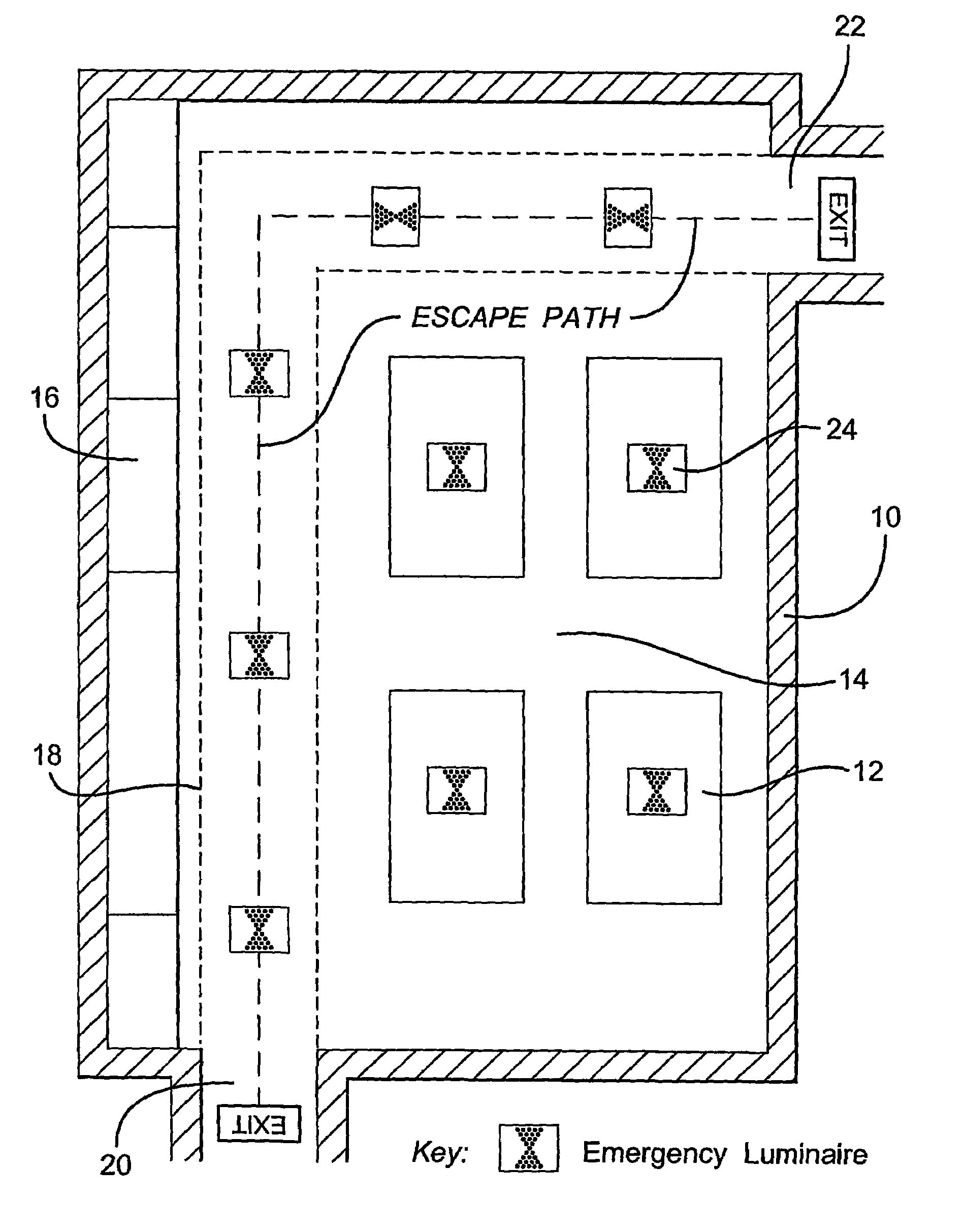
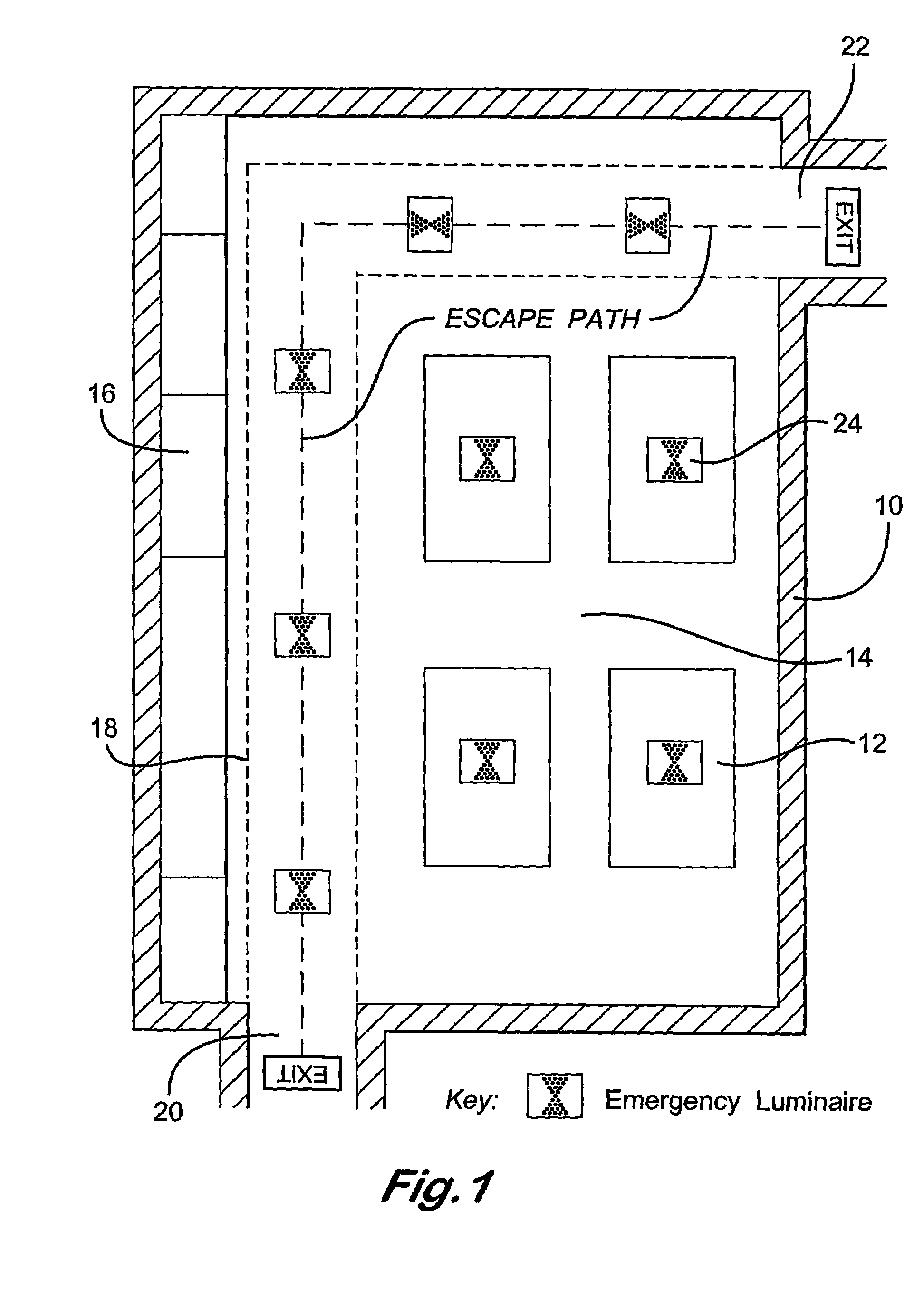
[0051]In the drawings, FIG. 1 shows a sales space 10 of a department store having sales counters 12 in an area 14, storage facilities 16 and a path 18 between an entrance 20 and an exit 22. In ordinary circumstances, the path 18 serves as a walkway, but in the event of a power failure or other emergency it also serves as an escape path. Emergency lighting luminaires powered by storage batteries are used to light both the path 18 and other areas such as the sales area 14. British standards, for example BS 5266-1:1999 require an even illumination of 1.0 lux and of width at lea...


PUM


Abstract

The invention relates to LED-based lamps, luminaires and lighting systems for buildings particularly, though not exclusively, for providing emergency light in the event of power failure. In particular it provides a light-emitting diode lamp comprising a support (26) and an array of light emitting diodes (58) on the support, an optical axis (72) passing through the middle of the array (58) and diodes increasing in number and increasing in inclination with distance from the optical axis (72). It also provides a luminaire (24) comprising a lamp as described above and a lens (30) having facets for generally un-deviated and un-reflected passage of light from off-axis diodes, and a building emergency lighting system comprising luminaires (24) as described above. In an alternative embodiment inclination of the light is through progressively increasing inclination of the facets.

Description

FIELD OF THE INVENTION[0001]The present invention relates to lamps, luminaires and lighting systems for buildings particularly, though not exclusively, for providing emergency light in the event of power failure.BACKGROUND TO THE INVENTION[0002]Building emergency lighting for use in the event of power failure is a requirement for public buildings, for example department stores, offices, hospitals, museums, libraries, sporting facilities and the like. Such lighting is required to operate for an extended period by power from internal storage batteries that are put into use when the mains power supply fails. Despite their hunger for power and limited life, such lighting devices have up to now relied on incandescent lamps or fluorescent tubes. Light-emitting diodes (LED's) have low power consumption and long life, but suggestions for their use for building lighting have been few, and the problem of emergency lighting of pathways and areas as opposed to individual signs has not been cons...

Claims


Application Information

Patent Timeline
Patent Type & Authority Patents(United States)
IPC IPC(8): F21S13/14F21S8/00F21S9/02F21V15/01F21V17/10F21V19/00G09F9/33G09F13/22H02J9/02
CPCF21S8/024F21S8/04F21S9/022F21V19/0045G08B7/066G09F9/33G09F13/22H02J9/02F21S8/02Y10S362/80F21V15/013F21V17/104F21V19/009F21W2111/00F21Y2101/02F21Y2111/005F21Y2113/00F21S8/022F21Y2115/10F21Y2107/30H05B35/00H05B45/00
Inventor ROZENBERG, SIMON GRANTLAWRY, IAN SHAUNLIMPKIN, GEORGE ALAN
Owner ROZENBERG SIMON GRANT
Learn More